Fulton VMP Webster Oil_Combo Burner User Manual
Page 33
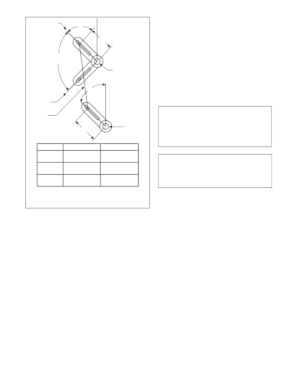
B
Low
Fire
High
Fire
Modulating
Range 90
o
A
Drive Arm
Jackshaft
Driven
Arm
D
C
Valve
(Air Damper,
FGR Valve...)
Linkage Arm
Dim
Smaller
Larger
Angle A
Slower LF driven
arm travel (D)
Faster LF driven
arm travel (D)
Length B
Reduce driven
arm travel (D)
Increase driven
arm travel (D)
Length C
Increase driven
arm travel (D)
Reduce driven
arm travel (D)
b. Decreasing the angle of the drive arm will slow the ini-
tial valve travel (and speed up the travel at high fire). This
would be done to get the air damper to match the fuel valve
action.
3. Fuel Cam Adjustments
The cam is used to adjust the intermediate fuel rate with
the low and high fire settings done by the linkage connec-
tions. The intermediate rates can be adjusted by turning the
adjusting screws in the clockwise direction to increase fuel
input and decrease the % O2 level in the flue gases. Turn-
ing the adjustment screws counterclockwise will decrease
fuel input and increase % O2 in the flue gases.
The following guidelines should be used for adjusting the
cam:
a. When adjusting the screws, the adjacent screws must
also be adjusted to provide a smooth contour from screw to
screw. When complete, the flexible strip between the adjust-
ing screws and the roller must come in contact with each
screw, providing a smooth transition from low fire to high
fire.
b. The end screws (or nuts) can be adjusted to hold the strip
against the screws, but should not deform the strip.
c. There should be no upsets in the profile, where the flex-
Figure I-1
Linkage Adjustments
ible strip is required to move to a screw position where
it is initially not in contact with the screw. Also, the
movement from one screw to the next cannot be too
large (more then 1/8”). This will cause the strip to flex
and will lead to premature failure of the strip.
d. The adjusting screws have a limited range of adjust-
ment. They can be turned in until they are flush with
the aluminum bar and adjusted out until the side wash-
ers of the roller contact the aluminum bar.
e. If any adjusting screw does not turn with some re-
sistance, the cam must be replaced.
f. When the cam adjustment is complete, the retention
plate must be installed. The retention plate will help
insure that the fuel valve position will not get far from
its ideal position, even with interference or sticky valve
operation.
WARNING
IF THE CAM ADJUSTING SCREWS DO NOT HAVE
RESISTANCE TO TURNING, THE CAM SHOULD
BE REPLACED, AS THE SCREWS MAY CHANGE
POSITION. FAILURE TO CHANGE A DEFECTIVE
CAM MAY RESULT IN INJURY OR DEATH.
CAUTION
LARGE CHANGES FROM ONE ADJUSTING
SCREW TO ANOTHER WILL RESULT IN PREMA-
TURE FAILURE OF THE CAM AND MAY PREVENT
THE BURNER FROM OPERATING PROPERLY.
g. If the contour has a sharp rise in the cam screw pro-
file, trying to open the valve very quickly in the first few
screws, the linkage should be readjusted to cause the
air damper to open slower (make the jackshaft drive
arm more parallel to the linkage rod). Likewise, the op-
posite contour can be corrected by speeding up the air
damper drive (Figure I-1). The final cam screw profile
should be close to the profile of the cam with no abrupt
changes.
4. FGR Adjustments
Flue gas is recirculated back into the burner to reduce
the flame temperature, which reduces the NOx level.
High quantities of flue gas result in lower NOx levels,
but can also result in flame instability if there is too
much FGR. Natural gas fuel can handle larger quanti-
ties of flue gas than oil and can have much lower NOx
levels as a result. Generally, the NOx levels only apply
to gas firing and oil firing is not adjusted for NOx levels.
There may be exceptions to this, and the orders details
should be reviewed to identify any special combustion
requirements.
Dual fuel units may need additional adjustments and
compensation to handle the different FGR rates be-
tween natural gas and #2 fuel oil. Units that require
gas NOx levels above about 45 ppm can operate with
the same quantity of FGR on both fuels and no addi-
tional controls or adjustments are needed. Burners
Page 33
Startup and Operating Adjustments
JB Manual