Configuring the burst rise and fall parameters, Using user–defined burst shape curves – Agilent Technologies E8267D PSG User Manual
Page 202
188
Chapter 7
Custom Real Time I/Q Baseband
Working with Burst Shapes
Burst shape maximum rise and fall time values are affected by the following factors:
•
the symbol rate
•
the modulation type
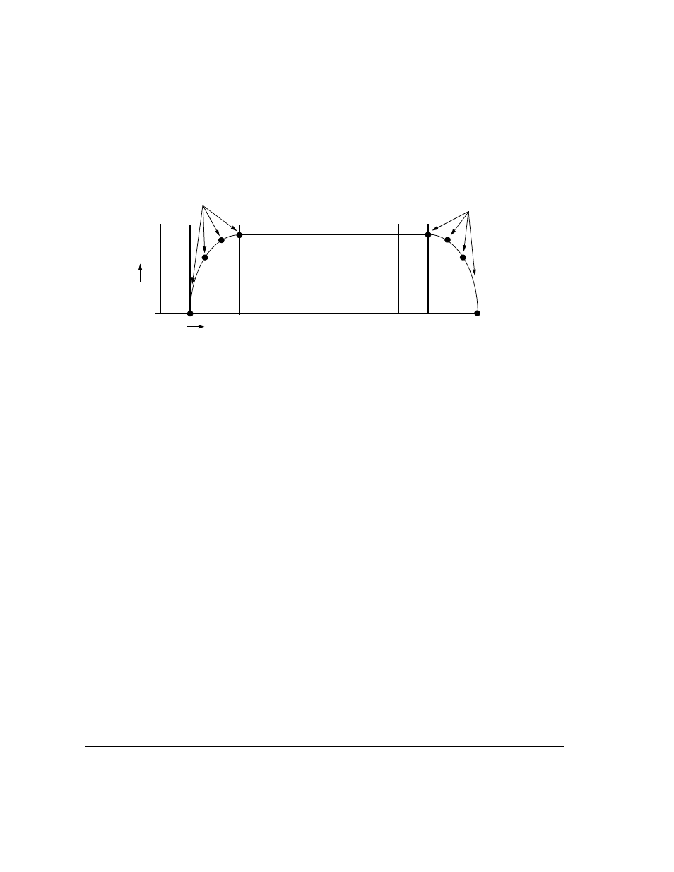
When the rise and fall delays equal 0, the burst shape attempts to synchronize the maximum burst
shape power to the beginning of the first valid symbol and the ending of the last valid symbol.
If you find that the error vector magnitude (EVM) or adjacent channel power (ACP) increases when
you turn bursting on, you can adjust the burst shape to assist with troubleshooting.
Configuring the Burst Rise and Fall Parameters
1.
Press
Preset
.
2.
Press
Mode
>
Custom
>
Real Time I/Q Baseband
>
Burst Shape
.
3.
Press
Rise Time
>
5
>
bits
.
4.
Press
Rise Delay
>
1
>
bits
.
5.
Press
Fall Time
>
5
>
bits
.
6.
Press
Fall Delay
>
1
>
bits
.
This configures the burst shape for the custom real–time I/Q baseband digital modulation format. For
instructions on creating and applying user–defined burst shape curves, see
User–Defined Burst Shape Curves” on page 189
Using User–Defined Burst Shape Curves
You can adjust the shape of the rise time curve and the fall time curve using the Rise Shape and
Fall Shape
editors. Each editor enables you to enter up to 256 values, equidistant in time, to define
the shape of the curve. The values are then resampled to create the cubic spline that passes through
all of the sample points.
The Rise Shape and Fall Shape editors are available for custom real–time I/Q baseband generator
waveforms. They are not available for waveforms generated by the dual arbitrary waveform generator.
0
1
Pow
e
r
Rise
Delay
Rise
Time
Fall
Time
Fall
Delay
Time
User–Define
d Values
User–Define
d Values