Liquid Controls SP3000 User Manual
Page 54
54
RS-232 OPERATING INSTRUCTIONS
GENERAL
This chapter summarizes operation of the SP3000 MASS FLOW COMPUTER with a remote terminal. It is
recommended that you read the preceding chapters of the Operating Instructions. You should be familiar with the
format and methods used in setting up the basic instrument before using the RS-232 communications option.
Setting up the RS-232 Link
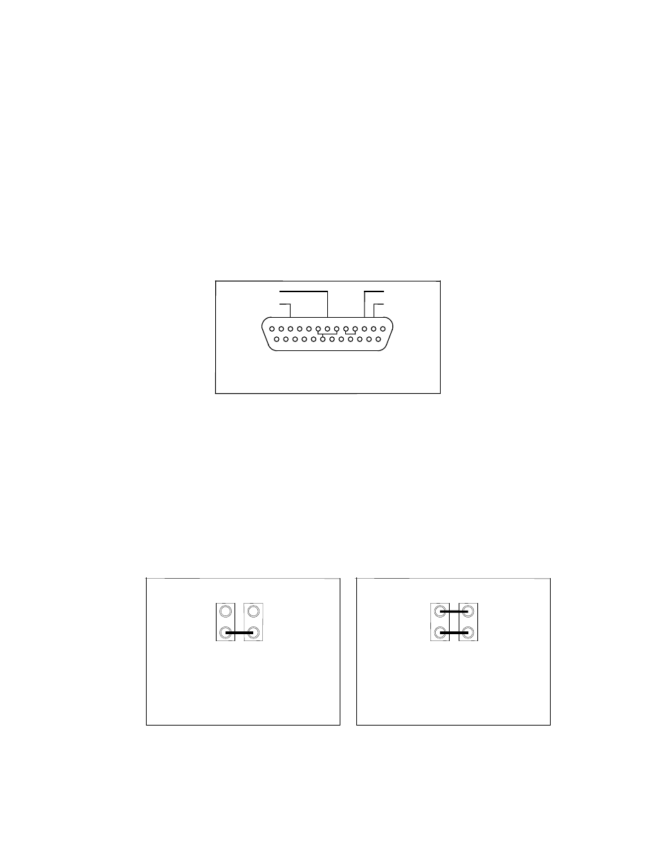
The RS-232 connector is a standard 25 pin connector, and it is located at the rear of the instrument. Figure 1
shows a wiring diagram for the Sub-D 25 Pin connector. Standard inputs must present a load of 3000 to 7000
Ohms. A voltage level of +3V to +25V (reference to signal ground) is read as a “Space” or “0” and indicates an
active state (does not assert a control line). Outputs must send a voltage of +15V to +25V (reference to signal
ground) for a “Space” and a voltage of -5V to -25V for a “Mark” when loaded with a 3000 Ohm load to signal
ground. Outputs must be capable of being shorted to other signal lines without burning out. It is normally
recommended that cable length be limited to 50 feet.
GROUND (7)
PRINTER BUSY (11)
TRANSMIT (3)
RECEIVE (2)
PINS 6, 8, AND 20 ARE JUMPERED TOGETHER
PINS 4 AND 5 ARE JUMPERED TOGETHER
1
2
3
4
5
6
7
8
9
10
11
12
13
14
15
16
17
18
19
20
21
22
23
24
25
Fig 1
Activating the Printer Busy Line on the SP3000
Two jumpers are needed to activate the printhead busy option on the RS-232 card. These jumpers are located on
the RS-232 card to the left of the 25 pin connector (looking from the back).
If Jumper 1 (JP1) is connected, the handshake option is activated. The handshake line is Pin #11 on the
RS-232 25 pin connector. Refer to Fig. 2 below.
Jumper 2 (JP2) determines whether Pin #11 is high or low when the printhead is busy. If (JP2) is installed,
then Pin #11 goes high when the printhead is busy. Refer to Fig. 3 below.
Be sure to follow case disassembly and other handling procedures outlined in this manual.
Connect JP1 to
activate option
Connect JP2 to indicate that the
printhead is busy when
Pin #11 is high
JP2
JP1
Fig 2
Fig 3
JP2
JP1