Installation – Liquid Controls SP3000 User Manual
Page 10
10
1.8
DATA DISPLAY AND KEYPAD
Internal 2 line by 20 character dot matrix LCD display. Sealed, 16 key panel featuring numeric keys 0-9,
plus the following keys:
A
Advance through menus
B
Back up through menus
C
Cancel current menu selection
D
Decimal point key
ENT
General purpose enter or recall data key
CLR
Data clear key
INSTALLATION
2.1
MOUNTING THE INSTRUMENT
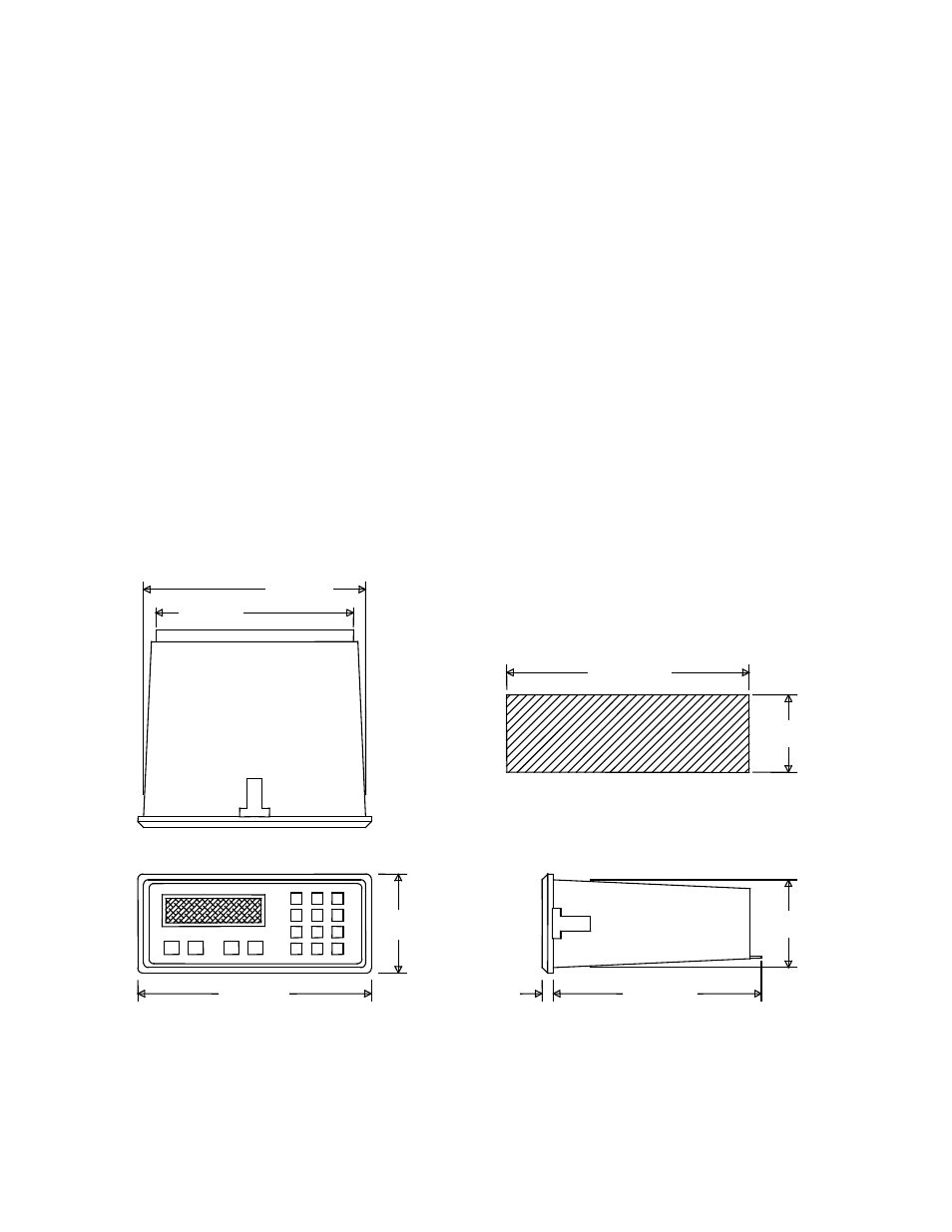
The Model SP3000 can be mounted in a user panel greater than 0.047” (1.2mm) and less than 0.187”
(4.7mm) thick. Figure 2-1 shows the cutout dimensions, bezel size, and depth needed for the instrument.
Be sure to provide additional space for cabling and connections behind the instrument (approximately 1.0”).
Additionally, all wiring to the back of the instrument should have sufficient service loops to allow for the
easy removal of the instrument from the panel.
Slip the gasket provided over the rear of the instrument case and slide it forward until it engages the inner
surface of the front bezel, slide the instrument into the panel opening. Install the screws provided in the
mounting brackets and insert in the slots located on all four sides of the instrument. Tighten the screws to
firmly secure the bezel and gasket up against the panel.
CAUTION: Do not over tighten mounting screw brackets
7.055 (179.2)
7.349 (186.7)
(63.4 +/- .25)
2.495 +/- .010
(187.0 +/- .25)
7.365 +/- .010
(13.5)
.525
6.000 (152.4)
(62.9)
2.480
(83.9)
3.305
(207.5)
8.170
C
0
E
9
8
7
6
5
4
3
2
1
D
C
B
A
PANEL CUTOUT DIMENSIONS
Figure 2-1
Dimensional Layout