2 switch settings – Controlled Products Systems Group 6050-080 User Manual
Page 36
Page 26
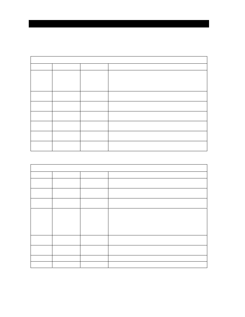
The two DIP-switches located on the circuit board are used to program the operator to operate in
various modes and to turn on or off various operating features. Whenever a switch setting is
changed, power to the operator must be turned OFF and then turned back on for the new setting to
take affect. Check and review ALL switch settings prior to applying power to the operator.
3.2 SWITCH
SETTINGS
SW 1 (TOP SWITCH)
SWITCH FUNCTION SETTING
DESCRIPTION
1 and 2
Relay and
Lock Power
1-OFF 2-OFF
1-OFF 2-ON
1-ON 2-OFF
1-ON 2-ON
Relay activated only when gate is FULL OPEN.
Relay activated whenever gate is NOT CLOSED.
Relay activated, magnetic lock power OFF when gate is
OPENING and OPEN.
Relay activated when gate is OPENING and CLOSING.
3 Open
Loop
Logic Output
OFF
ON
Output of loop detector in OPEN port is switched to terminal 12.
Output of loop detector in OPEN port feeds directly to processor.
4 Auto-Close
Timer
OFF
ON
Auto-close timer is OFF. Manual input required to close gate.
Auto=close timer is ON. Adjustable from 1-23 seconds.
5 Slide
Gate
Swing Gate
OFF
ON
Switch is in the OFF position for slide gate operators.
Switch is in the ON position for swing gate operators.
6 3-Button
Control
OFF
ON
Switch must be OFF when 3-button control is used.
Switch must be ON when single button control is in use.
7 Bi-parting
Gates
Single Gate
OFF
ON
Switch is OFF when bi-parting (master-slave) gates are used.
Switch is ON for single gate operation.
8 Tamper
Protect
OFF
ON
Tamper protect is turned OFF.
Tamper protect is turned ON.
SW 2 (BOTTOM SWITCH)
SWITCH FUNCTION SETTING
DESCRIPTION
1 Direction
Master
OFF
ON
Changes direction of MASTER operator. Set so that the operator
runs in the OPEN direction upon initial activation after power-up.
2 Direction
Slave
OFF
ON
Changes direction of SLAVE operator. Set so that the operator
runs in the OPEN direction upon initial activation after power-up.
3 Self
Test
OFF
ON
Normal operation.
Self test. Operator must be disconnected from gate to run test.
4 Motor
Control
OFF
ON
Switch is OFF when both master and slave operator motors are
powered from main terminals 4 and 5. Applies to operators
originally manufactured with 4501, Rev O boards or lower).
Switch is ON when slave operator motor is powered from the
slave motor terminals. Applies to operators manufactured with
4501, Rev P boards and higher.
5 Shadow
Input
OFF
ON
Terminal 15 is a standard REVERSE input with this switch OFF.
Terminal 15 is a SHADOW input with this switch ON.
6 Gate
Overlap
OFF
ON
Master and slave operators start at the same time.
Slave operator starts 1-2 seconds prior to the master operator.
7
Not Used
OFF
Leave in OFF position.
8
Not Used
OFF
Leave in OFF position.