2 secondary entrapment protection device wiring – Controlled Products Systems Group 6050-080 User Manual
Page 28
Page 18
2.2.2 SECONDARY ENTRAPMENT PROTECTION DEVICE WIRING
This swing gate operator uses an inherent entrapment sensing system (Type A) as the secondary
entrapment protection device. Additional external entrapment protection may be added to insure a
safe vehicular gate operating system. Additional inputs are available for non-contact sensors.
Secondary entrapment protection may be provided by a combination of non-contact (Type B1),
contact (Type B2) and inherent adjustable clutch (Type C) devices. See Section 5.3 for a list of
acceptable secondary entrapment protection devices.
• Disconnect power to the gate operator before installing the non-contact sensors.
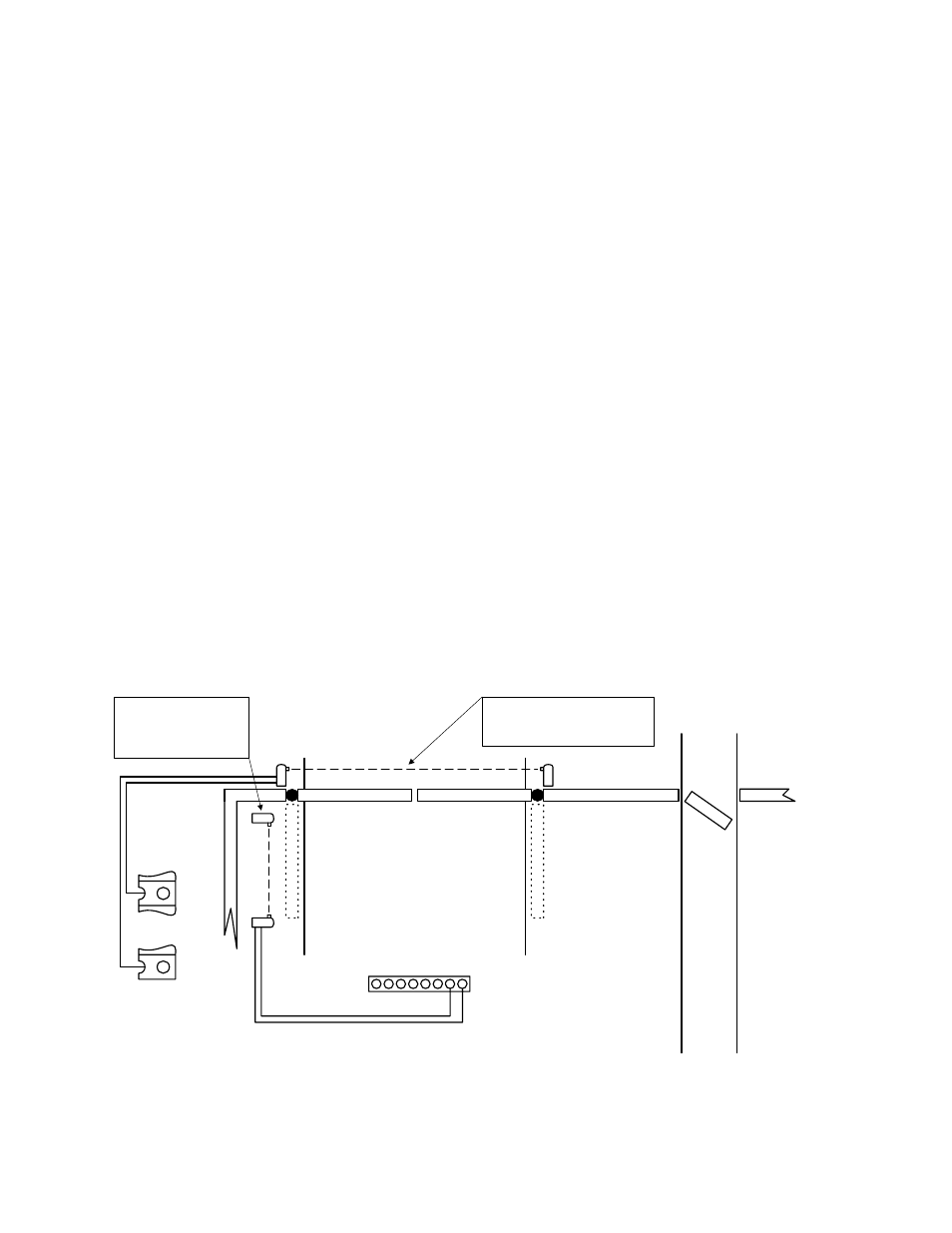
• See Figure 27 for suggested placement of sensors. (Diagram is for illustration purposes only.
Actual placement of sensors is dependent on the installation requirements).
• One or more non-contact sensors should be located where the risk of entrapment or
obstruction exist such as the perimeter reachable by a moving gate or barrier.
• Use only U.L. listed (or equivalent) non-contact sensors.
• Connect the non-contact sensors as shown below. Inputs from the photo-beam to the circuit
board are Normally Open (N.O.). Diagram does not illustrate power wiring to the photo-
beams. Refer to the photo-beam wiring diagram and installation instructions for proper
connection of photo-beam power.
• Photo-beam input to MAIN TERMINALS 15 and 20 will REVERSE travel of gate when
activated during the CLOSE CYCLE ONLY.
• Photo-beam input to AUXILIARY TERMIANLS 7 and 8 will STOP gate travel in either the
OPENING or CLOSING cycle. Gate will resume normal operation when photo-beam is no
longer activated.
Pedes
trian Ac
c
es
s
Roadway
Fenc
e
Fence
Gate
Gate
Standard reverse beam prevents
gate from hitting obstructions
during the close cycle.
Open protect beam
protects area between
gate and adjacent fence
during open cycle.
Auxiliary Terminal Strip
Alarm Signal
Alar
m Res
et
Common
Gate Tracker Output
Gate Tracker Output
Gate Tracker Output
Photo-Beam
Common
15
20
Main T
er
minal
Str
ip
Figure 27