2 connecting arm – Controlled Products Systems Group 6050-080 User Manual
Page 19
Page 9
4. Slide the connector assembly (Figure 14) onto the crank arm so that the flange is away
from the gate.
5. The connector assembly must be positioned on
the crank arm at the correct distance from the
operator shaft to allow the gate to open a full 90º.
To determine this measurement, refer back to
SECTION 1.2. Measure the distance from POINT
A1 to POINT A2 then divide this measurement by
2. The result is the crank arm assembly length.
(Table 3 determines this measurement for the
three different X measurements provided in
SECTION 1.2.)
6. Adjust the connector assembly on the crank arm so that the distance from the center of
the operator output shaft to the center of the pivot on the connector assembly is equal to
the result of the computation in step 4 above then tighten the setscrews to secure the
connector in place.
7. The length of the crank arm / connector assembly is dependent on the X measurement
that was selected in SECTION 1.2. This length can be calculated by using the
Pythagorean Theorem A
2
+ B
2
= C
2
to find the hypotenuse (A1, A2) of the right triangle
formed by the gate hinge point, point A1 and point A2. Once the hypotenuse is found,
divide it by 2 to get the required crank arm / connector assembly length. The crank arm
lengths in Table 3 where determined by this method.
1.4.2 CONNECTING
ARM
1.
Place the gate in the full closed position.
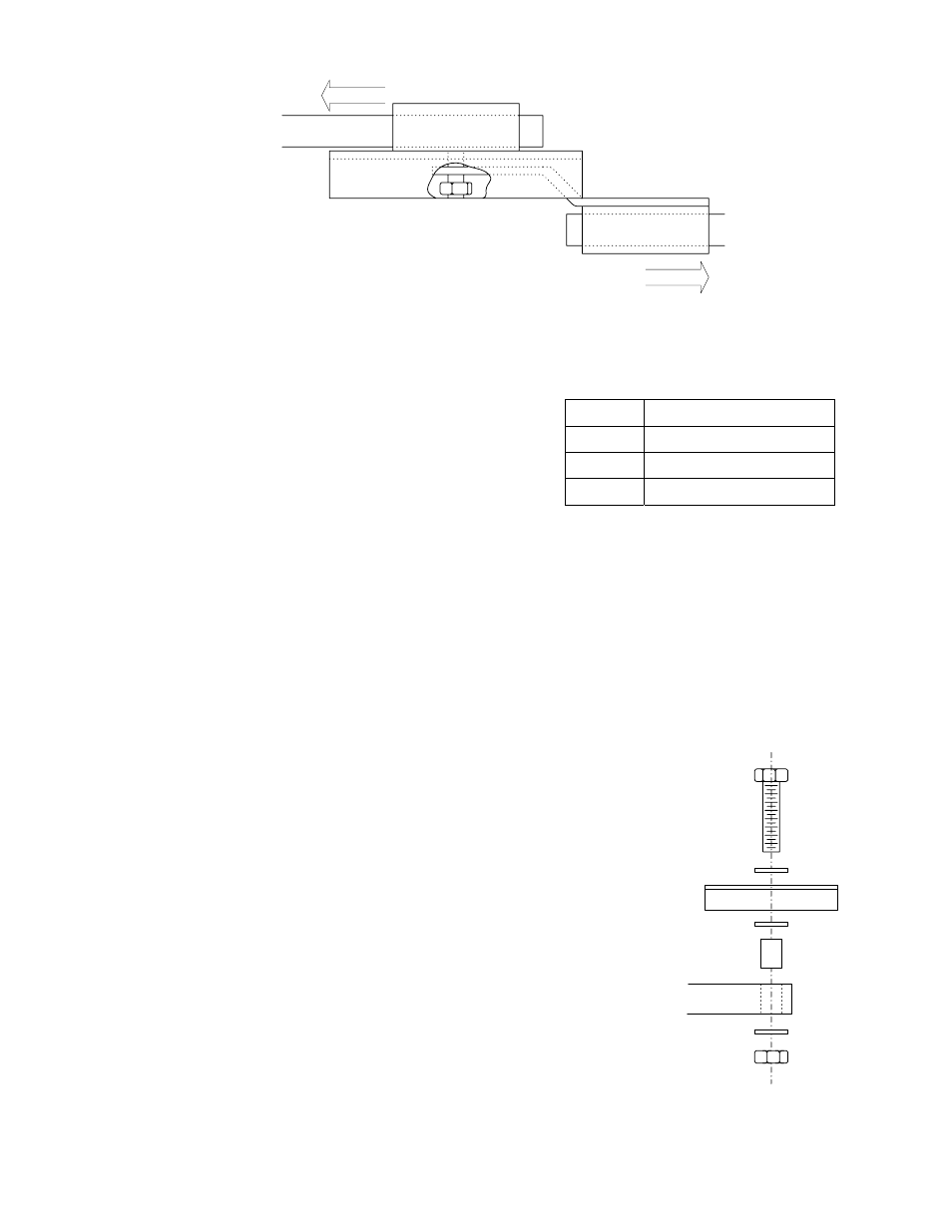
2.
Once the crank arm assembly length is set, slide
one end of the connector arm through the connector
assembly and attach the other end to the gate
bracket as shown in Figure 15. Attach the arm to
the bottom side of the gate bracket.
3.
Be sure that the gate is fully closed and then tighten
the three setscrews in the connector assembly to
lock the connecting arm in place.
X CRANK
ARM
34 24.04
30 21.21
26 18.38
To Gate
To Operator
Bolt 1/2-13 x 2 1/4
1/2 Washer
Gate Bracket
Bushing
Connecting Arm
Lock Nut 1/2-13
1/2 Washer
1/2 Washer
Table 3
Figure 14
Figure 15