8 auxiliary terminal description – Controlled Products Systems Group 6050-080 User Manual
Page 34
Page 24
21.
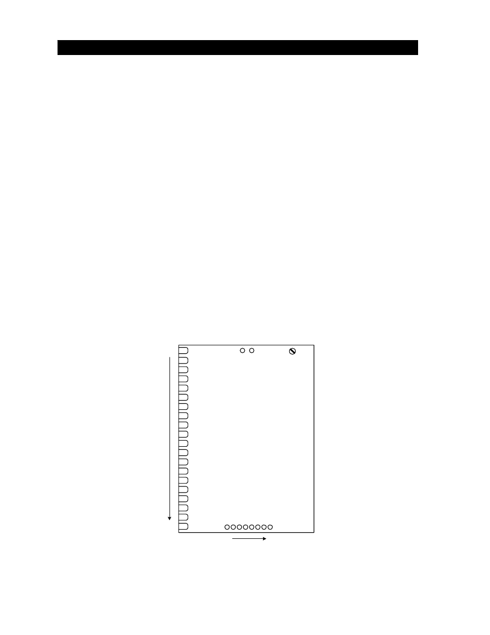
The auxiliary terminal is located on the 4502 circuit board just to the right of main terminals 18 and
19. Auxiliary terminals are numbered 1 through 8.
1. ALARM
OUTPUT
Provides power to activate the entrapment alarm.
2.
ALARM RESET INPUT
Input to reset the operator after an entrapment alarm.
3. COMMON
Common for alarm output and alarm reset input.
4. TRACKER
DATA
Supplies gate operator data to Tracker expansion board (P/N 2351-010). Refer to
the Tracker Installation and Wiring Manual for detailed information.
5. TRACKER
DATA
Supplies gate operator data to Tracker expansion board (P/N 2351-010). Refer to
the Tracker Installation and Wiring Manual for detailed information.
6. TRACKER
DATA
Supplies gate operator data to Tracker expansion board (P/N 2351-010). Refer to
the Tracker Installation and Wiring Manual for detailed information.
7. PHOTO-BEAM
INPUT
This input will cause the gate operator to stop when activated in either the opening or
closing cycles. The gate operator will remain stopped until the photo-beam input is
cleared, at which time the operator will resume normal operation.
8. COMMON
Common for photo-beam input.
2.8 AUXILIARY TERMINAL DESCRIPTION
MAIN TERMINALS
1
20
AUXILIARY TERMINALS
1
8
SL
AVE MOTOR
TERMINAL
S
GROUND L
UG
Figure 34