2 pad mount operator – Controlled Products Systems Group 6050-080 User Manual
Page 14
Page 4
X Y
Gate
Width
34 32 14
Ft.
30 28 12
Ft.
26 24 10
Ft.
1.2.2 PAD
MOUNT
OPERATOR
1.
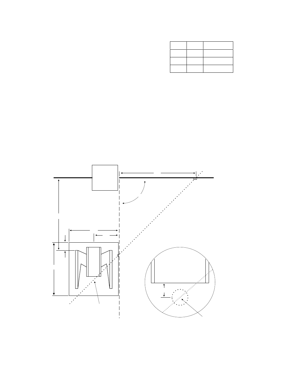
Using Table 2 and Figure 5 determine the location
of the concrete pad and mounting plate. The
location of the pad and base plate and the Y
measurement is dependent on the X
measurement that you choose.
2.
X is the measurement from the center of the gate
hinge to the center of the gate bracket and
defines the position of the A1 and A2 points.
3.
Once the location of the pad and base plate has been determined, construct a form
for the concrete pad according to Figure 6. Note that the depth of the pad is
determined by soil conditions and local building codes. The pad is sized so that there
is four (4) inches of concrete around the mounting plate when it is installed on the
pad.
4.
IMPORTANT!! Be sure that the top of the pad is level.
5.
Let the concrete cure for 48 hours before proceeding with the installation of the gate
operator.
6.
Anchor the concrete mounting plate to the pad using eight (8) 3/8 x 3 sleeve anchors
(not supplied). It is important that the concrete base plate is located correctly on the
pad so that the A1-A2 line will intersect the operator output shaft as shown in Figure
5.
Table 2
X
Gate Closed
Gate Open
90°
Fence
Pilaster
A2
A1
Y
Gate
Bracket
12
C
oncrete
Mounting Pad
24
26
Point C is centered
1.5 inches in front of
the mounting plate.
See detail A.
A1-A2 Line
Output
Shaft
Point C
Detail A
1.5
4
Figure 5