2 pad mounted operators – Controlled Products Systems Group 6050-080 User Manual
Page 17
Page 7
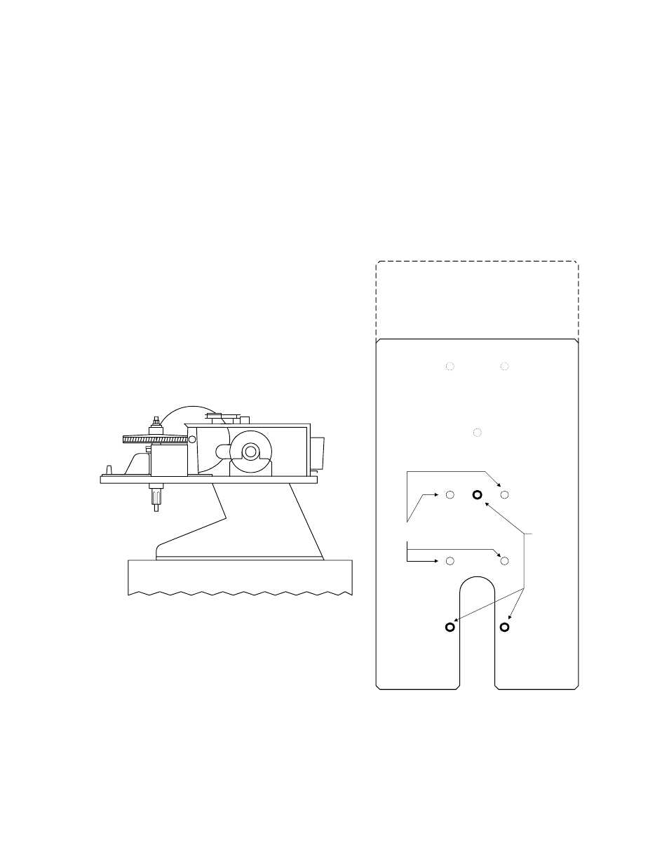
1.3.2 PAD
MOUNTED
OPERATORS
1.
Place the operator on the mounting plate so that the four (4) mounting holes are in
alignment and the output shaft extends in front of the mount plate base (Figure 10).
2.
Bolt the operator to the mounting plate using two (2) 3/8-16 x 1 bolts, two (2) 3/8
washers, and two (2) 3/8-16 nuts in the holes marked A (Figure 11).
3.
Use the remaining hardware, two (2) 3/8-16 x 1 1/4 bolts, two (2) 3/8 washers, and
two (2) 3/8-16 nuts in the holes marked B (Figure 11).
4.
Use the three (3) 5/16 lock nuts to secure the bolts from the bottom of the operator
base to the mount plate base. These bolts are labeled "Bolt" in Figure 11.
5.
Route conduits into the operator at this time.
6050 / 6100
Operator Base
Nut Plates
Bolt
Mounting
Hole
Bolt
Bolt
6100 W/Battery Back-Up
Operator Base
A
A
B
B
Figure 10
Figure 11