3 loop detector wiring – Controlled Products Systems Group 6050-080 User Manual
Page 29
Page 19
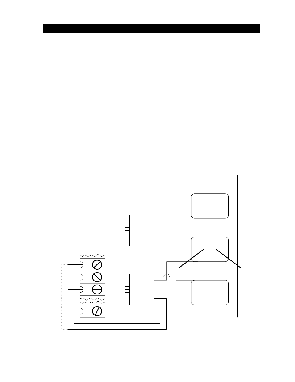
• Loop detector wiring is shown for DoorKing model 9405 and 9406 Plug-In loop detectors
only. If other loop detectors are used, refer to the installation instructions supplied with those
detectors for wiring requirements.
• If other loop detectors are used, all inputs to the terminal strip are NORMALLY OPEN. Use a
separate power supply to power external detectors. Be sure that power is turned off prior to
making any connections to the terminal strip.
• Loop layout shown is for a typical swing gate application with two-way traffic or one-way exit
only traffic. For one-way entry only traffic, the open loop is replaced with a second reverse
loop wired in series with the first reverse loop. The 9506 detector is not needed in this
application.
• Refer to the separate Loop Information Manual (available from DoorKing) for instructions on
installing loops or preformed loops.
• For correct SHADOW LOOP operation, jumper wire must be placed from terminal 15 to
terminal 16, and SW1, switches 1 and 2 must be OFF. If a magnetic lock is used, set switch
1 ON and switch 2 OFF.
• NOTE: Output of Shadow Loop Detector may be connected directly to terminal 15 (dotted
line - no jumper required between 15 and 16) if SW 2, switch 5 is ON. However, with this
switch ON, terminal 15 becomes a shadow input (active only when the gate is FULL OPEN)
and all reversing devices connected to terminal 15 will operate as shadow devices. If this is
not desirable, wire the shadow loop detector as instructed in the above bullet point.
2.3 LOOP
DETECTOR
WIRING
Reverse Loop
Shadow Loop
Open or
Reverse Loop
Loop Detector
P/N 9406-010
Loop Detector
P/N 9405-010
TB 1
TB 2
TB 1
20
17
16
15
C
NO
Pl
ug Into
OPEN Po
rt
Pl
ug Into
REVERSE Po
rt
Figure 28