Controlled Products Systems Group 6050-080 User Manual
Page 13
Page 3
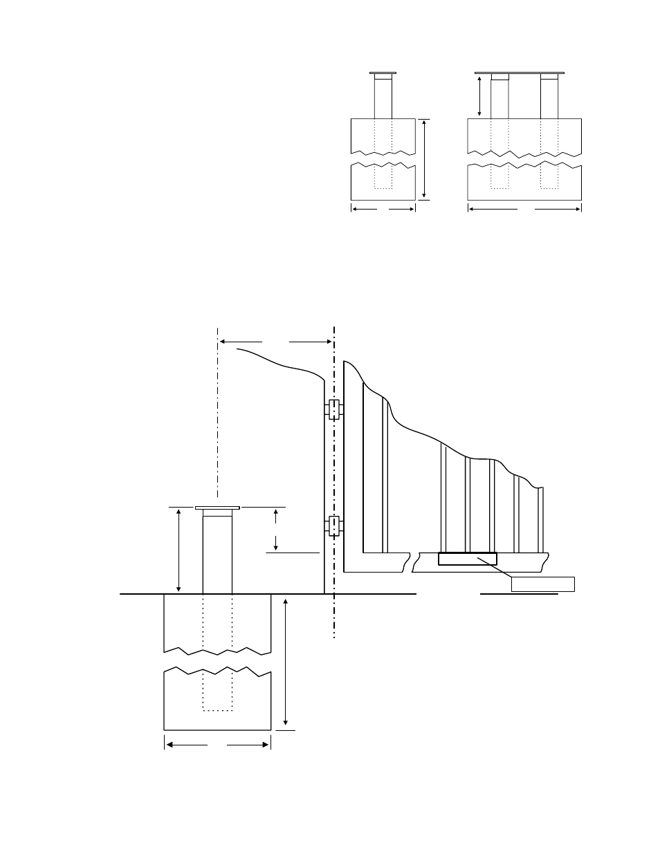
• The concrete pad is sized so that there is
a minimum of four (4) inches of concrete
from the outside edge of the mounting
pipes.
• The height requirement is determined by
adjusting the mounting plate / pipe
assembly so that the top of the mounting
plate is 4 3/4 inches above the top of the
gate rail (Figure 4). This will allow you to
mount the gate bracket onto the bottom
rail of the gate and will keep the crank and
connecting arms level (see page 8, Figure
12).
• The top of the mounting plate must be at
least six (6) inches above the ground. If it is less than this, the gate arms will scrape the
ground when the operator starts.
• It is very important that the operator mounting plate is level.
D
e
te
rmined by
s
o
il
c
ondit
ions
and loc
a
l c
ode
Height determined by
installation requirements
11
19.5
Figure 4
11
12
Gate Hinge
Gate Frame
Determ
ined by soil
conditions and local code
4 3/4
Ground Level
Min
imu
m He
ig
h
t
6 Inches
Gate Bracket
Figure 3