4 magnetic lock wiring, 1 direct power, 2 indirect power – Controlled Products Systems Group 6050-080 User Manual
Page 30
Page 20
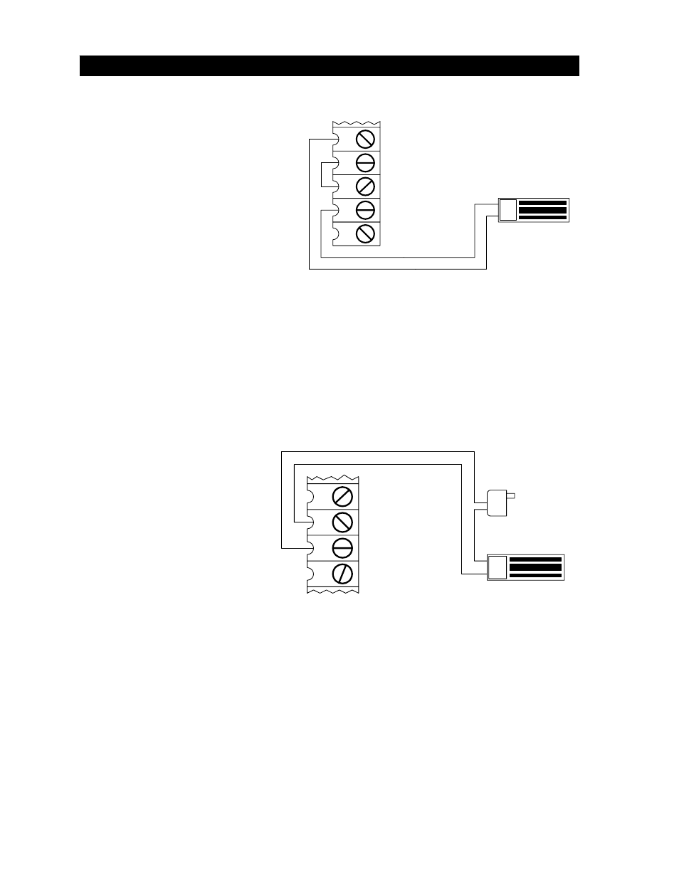
2.4.1 DIRECT
POWER
• Connect the magnetic lock as
shown in Figure 29.
• 24-volt magnetic lock is connected
directly to terminals 16 and 19 on
the 4502 circuit board. Place a
jumper wire from terminal 17 to
terminal 18. 24-volt magnetic lock
power is provided at terminals 18
and 19.
• Set relay contact shorting pin to
NC (normally closed) operation
(see 3.1).
• SW1, switch 1 must be in the
ON position and SW1, switch
2 must be in the OFF position
when connecting a magnetic
lock in this manner.
2.4.2 INDIRECT
POWER
• Connect the magnetic lock as
shown in Figure 30.
• Requires the use of a DC
transformer for magnetic lock
power.
• Relay shorting pin on the
4502 circuit board must be set
for NC (Normally Closed)
operation (see 3.1).
• SW1, switches 1 and 2 can be
set in three different ways:
1. Switch
1
OFF, Switch 2 ON
2. Switch
1
ON, Switch 2 OFF
3. Switch
1
ON, Switch 2 ON
2.4 MAGNETIC LOCK WIRING
18
17
16
15
Magnetic Lock
Set voltage select pin
to match power supply
Magnetic Lock
Power Supply
12 or 24 VDC
Figure 29
Figure 30
18
19
20
Magnetic Lock
Set voltage select pin
to 24 Volt
16
17