Controlled Products Systems Group 6050-080 User Manual
Page 15
Page 5
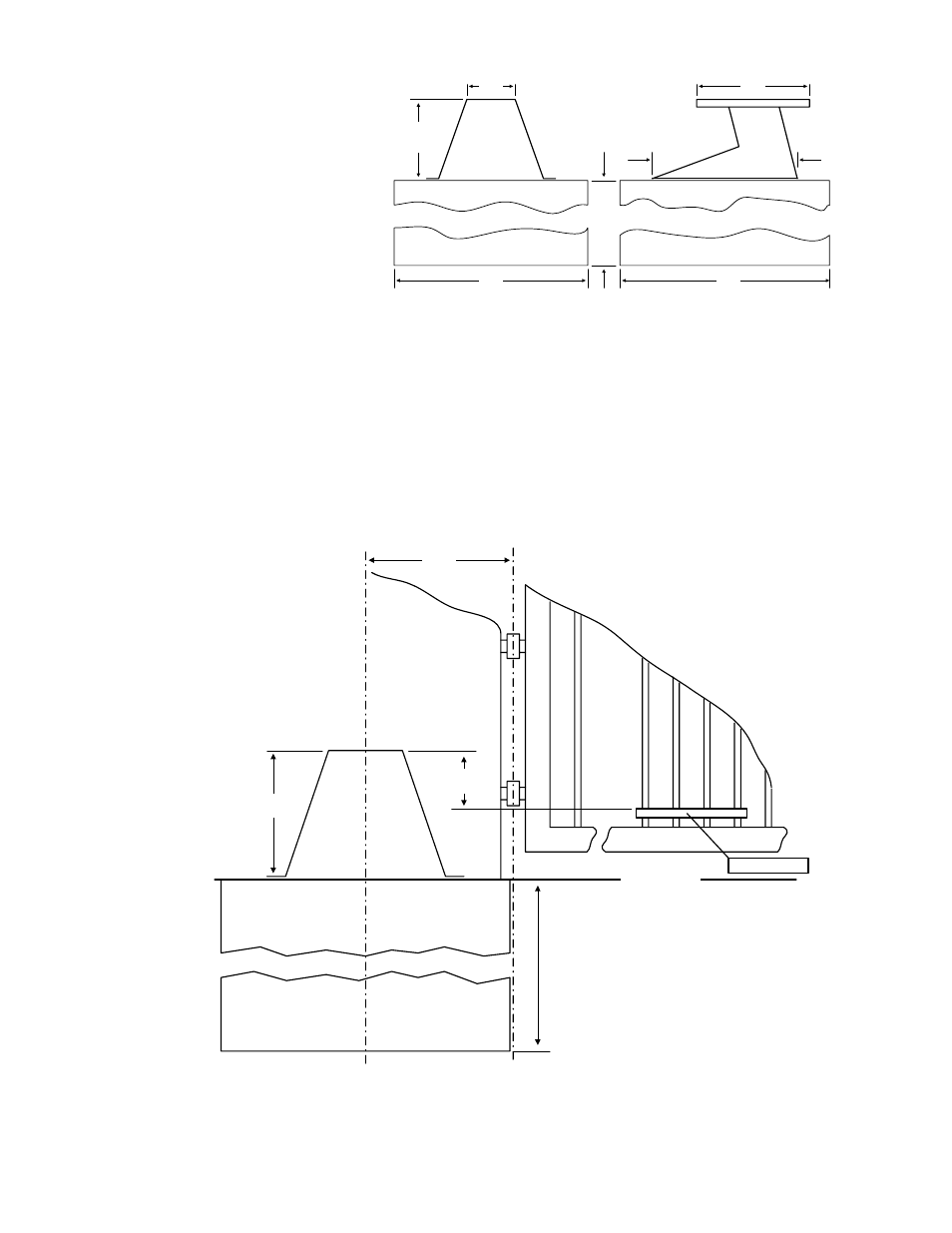
• The concrete pad is sized
so that there is a
minimum of four (4)
inches of concrete around
the perimeter of the pad.
• Attach the gate bracket to
the gate so that the top of
the mounting plate is 4
3/4 inches above the top
of the gate bracket as
shown in Figure 7. This
will keep the crank and
connecting arms level
(see page 8, Figure 12).
• The height requirement can also be ascertain by placing the gate bracket so that it is 5 3/4
inches (10 1/2 - 4 3/4) above the bottom of the base plate, or above the top of the concrete
pad.
• The position of the gate bracket on the gate is directly related to the height of the concrete
pad above ground level. If allowed by local codes, the top of the concrete pad can be flush
with ground level as shown in Figure 7, which will allow the gate bracket to be lower on the
gate.
26
24
Determined by soil
conditions and local code.
5 1/2
14
10 1/2
18
Figure 6
Figure 7
12
Gate Hinge
Gate Fram
e
Deter
m
ined by
s
o
il
c
ondi
ti
ons
and l
oc
al
c
ode
Gate Bracket
Ground Level
4 3/4
10 1/2