CONTREX MLP-Drive User Manual
Page 66
3 - 28
Follower Mode - Analog Lead
The MLP-Drive can be scaled for Engineering Unit setpoint entry and Tach display
operation using the analog input for the lead signal. The following Control Parameters
give the MLP-Drive the necessary information for analog lead operation in Follower
mode.
Analog Input Allocation(CP-84)
Setting CP-84, Analog Input Allocation, to a value of "1" allocates the
analog input to be used as the lead source.
Follower Engineering Units (CP-21)
The actual value of the Follower Engineering Units if the system were to
operate with an analog lead level of 10.0 volts and a feedback of Max
RPM Feedback (CP-34). This is the maximum calibrated analog input
level (refer to Installation/Setup: Calibration, Analog Input Calibration).
Note: The analog input does not need to operate to 10.0 volts full scale to be
used for analog lead.
Max RPM Feedback (CP-34)
This is the maximum RPM of the feedback sensor shaft during system
operation.
PPR Feedback (CP-31)
The number of gear teeth or encoder lines on the follower feedback
sensor per revolution.
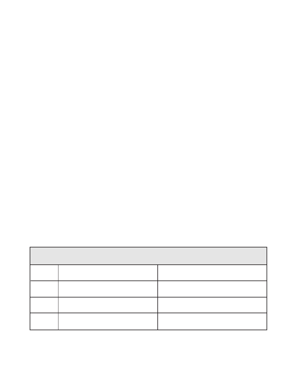
Table 3-19 Default Scaling Control Parameters
CP
Parameter Name
Parameter Value
CP-84
Analog Input Allocation
0
CP-21
Follower Engineering Units
1.000
CP-34
Max RPM Feedback
2000
CP-31
PPR Feedback
60