Outputs, Outputs -15, Drive output – CONTREX MLP-Drive User Manual
Page 31: Digital output 1
2 - 15
OUTPUTS
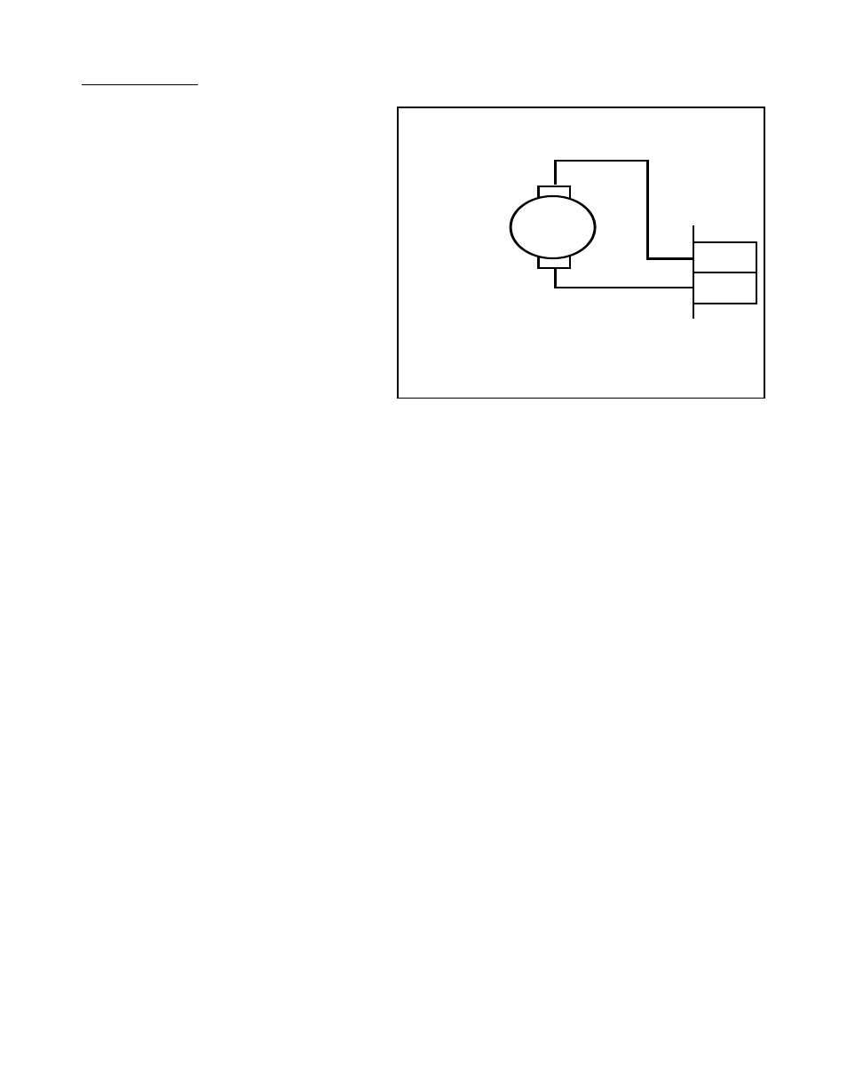
Drive Output
(J3 pins 1, 2)
Connect the Drive Output
(J3 pins 1, 2) to the armature leads
(A1 and A2) of your permanent
magnet, DC motor. If you reverse the
armature leads, then the direction of
the motor rotation also reverses.
Figure 2-17 Drive Output
Digital Output 1
(J5 pin 15, 17)
The Digital Output 1 can be programmed to activate as a function of various alarm
conditions or as a function of the drive enable logic. Refer to CP-10 for function
allocation of Digital Output 1.
NOTE: This is an open-collector relay driver. For specification details, see
References:
Appendix A
-
MLP–Drive Specifications
. Use an external DC power supply to
power the relays. Free-wheeling diodes are incorporated internally in the MLP–
Drive and do not need to be added externally.
1
2
J3
A1
A2
+
–
DC PM
Motor