Danger, Figure g-3 start/stop with armature contactor – CONTREX MLP-Drive User Manual
Page 193
G- 3
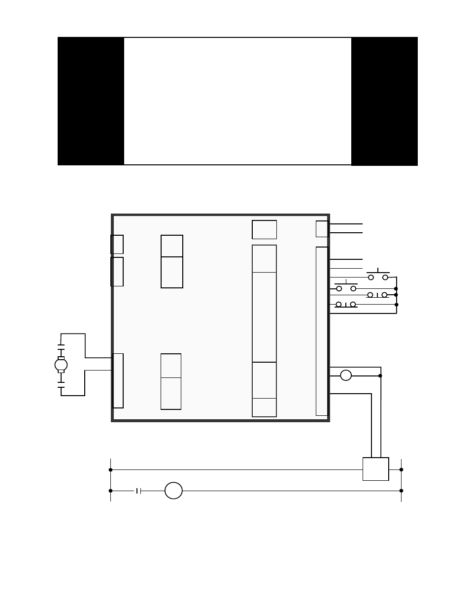
Figure G-3 Start/Stop with Armature Contactor
DANGER
This diagram is for conceptual purposes only!
Use safety equipment.
Make wiring connections carefully.
Incorrect use of equipment or connections
can cause injury or death.
DC PM
Motor
A1
A2
M1
M1
Neut
Line
K-R
M1
Armature
Contactor
+ —
12 Volt
Power
Supply
Feedback
Freq.
Run
Jog
R-Stop
F-Stop
K-R
LEAD_FQ
FDBK_FQ
COM
RUN
JOG
R–STOP
F–STOP
COM
MST / FOL
SETPT
SCRL_UP
SCRL_DWN
COM
V_DO
DIG_OUT1
DIG_OUT2
COM
ANAL_IN
COM
J1
J4
T / R +
T / R –
COM_AUX
RS485
COMM
I/O
PWR
A1 +
A2 -
L1
NEUT
GND
PE
AC
POWER
MOTOR
ARM
FREQ
INPUTS
DIGITAL
INPUTS
J5
DIGITAL
OUTPUTS
5V_DI
COM
J2
5V Ext
Pwr Supply
+
–
ANAL
IN
1
2
3
4
5
6
7
8
9
10
11
12
13
14
15
16
17
18
19
AUX
PWR
J3
1
2
3
5V
COM_AUX
1
2
1
2
1
2
3
4
5
+
-