Wiring and set up – GF Signet 2610 Process Optical Dissolved Oxygen Sensor User Manual
Page 5
5
2610 DO Sensor
Wiring and Set Up
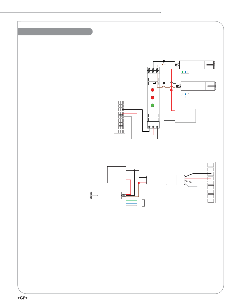
3-2610-31 to 8900 Set Up
1. Connect the 8058, 2610-31, and 8900 as shown in the diagram.
2. Press and hold ENTER key for 5 seconds.
3. The display should fl ash “System Setup”.
4. Press ENTER key.
5. Scroll to the desired channel for Dissolved
Oxygen.
6. Press
the
► key.
7. Enter the password.
8. Repeatedly press the ▼ key until the lower
line of the display reads “Other (4-20)”.
9. Press ENTER key.
10. The 8900 will warn that “Channel Data will
be Reset. Are you sure?” Press the ▼ key
so that “Yes” is fl ashing and press ENTER
key.
11. Simultaneously press the▲ and ▼ keys to
return to the Menu Directory.
12. Press the ▼ key to select the “Channel
Settings” menu and press ENTER key to
select.
13. Use the ▼ key to select the channel used
in step 5.
14. Press the ► key to change the label and press ENTER when done.
15. Press the ▼ key to select the
abbreviation.
16. Press the ► key to change the
label and press ENTER when
done. Press the ▼ key to select
the Units.
17. Press the ► key to change
the Units. The 2610 shipped
with default units of mg/L or
ppm, either can be used. Press
ENTER when completed.
18. Press the ▼ key to select the 4
mA Set Point.
19. Press the ► key to change the set point. By default the 4 mA set point for the 2610 is 0.0. Press the ENTER
key when complete.
20. Press the ▼ key to select the 20 mA Set Point.
21. Press the ► key to change the set point. By default the 20 mA set point for the 2610 is 20.0. Press the
ENTER key when complete.
22. Press the ▼ key to select the Decimal location.
23. Press the ► key and change the decimal position if desired. Press ENTER when complete.
24. Simultaneously press the ▲ and ▼ keys to exit out of the channel menu.
25. Continue programming other options in the 8900 or simultaneously press the ▲ and ▼ keys to return to the
View Mode.
6
7
8
9
10
11
12
13
14
+
-
3 2 1
6 5 4
7 8 9
Loop1
PWR
N/C
S L
DATA
3
Loop2
PWR
+GF+ SIGNET
8058-2
BLACK (5 VDC)
BLACK
BLACK
BLACK
RED
RED
WHITE (GND)
RED (S
3
L)
24 VDC
Regulated
Power Supply
DO Sensor 1
3-2610-31
No connection
DO Sensor 2
3-2610-31
No connection
8900 Sensor Inputs
BROWN
BROWN
RED
DO Sensor
3-2610-31
24 VDC
Regulated
Power Supply
BLACK
Input
4-20 mA
Output
S
3
L
SHIELD
(no connection)
Signet 8058 i-Go™
4-20 mA to S
3
L Converter
+GF+
4-20 mA input S
3
L Output
V–
V+
BROWN
GREEN
BLUE
WHITE
No connection
8058-1
8900 Sensor Inputs
6
7
8
9
10
11
12
13
14
BLACK
RED
WHITE
SHIELD
(no connection)
Wiring and Set Up