4 to 20 ma span adjustment, Ordering information – GF Signet 2450 Pressure Sensor User Manual
Page 4
Georg Fischer Signet LLC, 3401 Aero Jet Avenue, El Monte, CA 91731-2882 U.S.A. • Tel. (626) 571-2770 • Fax (626) 573-2057
For Worldwide Sales and Service, visit our website: www.gfsignet.com • Or call (in the U.S.): (800) 854-4090
For the most up-to-date information, please refer to our website at www.gfsignet.com
3-2450.090-1 Rev. K 05/13 English
© Georg Fischer Signet LLC 2013
6. 4 to 20 mA Span Adjustment
The 4 to 20 mA endpoint values are independent of one another and may be adjusted in the fi eld. For example, to reduce the 20 mA
endpoint value from the maximum full scale limit set at the factory, but to allow the 4 mA endpoint to remain at 0 psig, perform only the
steps listed in 6.2 below. NOTE: The RED wire, which is not connected during normal 4 to 20 mA operation, assumes an important role
in the following procedures.
6.1 To adjust the 4 mA endpoint in the fi eld:
• Carefully remove the heat shrink tube that is protecting the red wire.
• Expose the sensor to the pressure desired to correspond with 4 mA (any
pressure in the operating range).
• With power applied as described in Section 5, connect the RED wire to
the WHITE wire for 15 seconds.
(After about 10 seconds the output will drop to 3.6 mA and remain there
until the RED wire is disconnected.)
• Disconnect the RED wire from the WHITE wire; the 4 mA endpoint has
been adjusted.
NOTE:
The output will act as a switch if the 4 and 20 mA endpoints are set
very near to the same value.
6.2 To adjust the 20 mA endpoint in the fi eld:
• Expose the sensor to the pressure desired to correspond with 20 mA (any pressure in the operating range).
• With power applied as described in Section 5, connect the RED wire to the BLACK wire for 15 seconds.
(After about 10 seconds the output will rise to 22 mA and remain there until the RED wire is disconnected.)
• Disconnect the RED wire from the BLACK wire; the 20 mA endpoint has been adjusted.
NOTE:
The output will act as a switch if the 4 and 20 mA endpoints are set very near to the same value.
Minimum span is ±2% of maximum range.
• After adjusting the 4 to 20 mA span, protect the red wire by installing the provided wire nut.
• For easier re-spanning use the Signet 0250 USB to Digital (S
3
L) Confi guration/Diagnostic Tool.
6.3 To restore factory span:
• Disconnect power to the sensor. Wait 10 seconds to allow circuit to discharge.
• Connect the RED wire to the WHITE wire.
• Apply power as described in Section 5, but with the RED wire connected to the WHITE wire for 15 seconds.
(After about 10 seconds the output will drop to 3.6 mA and remain there until the RED wire is disconnected.)
• Disconnect the RED wire from the WHITE wire; factory settings have been restored.
• Replace cap on RED wire.
Mfr. Part No.
Factory Span
3-2450-7U
4 to 20 mA = 0 to 10 psig
3-2450-7L
4 to 20 mA = 0 to 50 psig
3-2450-7H
4 to 20 mA = 0 to 250 psig
7. Ordering
Information
Mfr. Part No.
Code
Description
3-2450-3U
159 000 683
10 psig, Digital (S
3
L),
1
/
2
in. Male Union, 15 ft Cable
3-2450-7U
159 000 906
10 psig, 4 to 20 mA,
1
/
2
in. Male Union, 15 ft Cable
3-2450-3L
159 000 682
50 psig, Digital (S
3
L),
1
/
2
in. Male Union, 15 ft Cable
3-2450-7L
159 000 908
50 psig, 4 to 20 mA,
1
/
2
in. Male Union, 15 ft Cable
3-2450-3H
159 000 681
250 psig, Digital (S
3
L),
1
/
2
in. Male Union, 15 ft Cable
3-2450-7H
159 000 910
250 psig, 4 to 20 mA,
1
/
2
in. Male Union, 15 ft Cable
3-8050-1
159 000 753
Universal Mount Junction Box
3-8052-1
159 000 755
¾ in. NPT mount junction box
3-9000.392-1
159 000 839
Liquid tight connector kit, NPT (1 piece)
3-9000.392-2
159 000 841
Liquid tight connector kit, PG 13.5 (1 piece)
3-9900.396
159 001 701
Angle Adjustment Adapter Kit
5523-0322
159 000 761
Cable, 3 conductor + shield, 22 AWG, black/red/white/shield
3-0250
159 001 538
USB to digital (S
3
L) confi guration/diagnostic tool
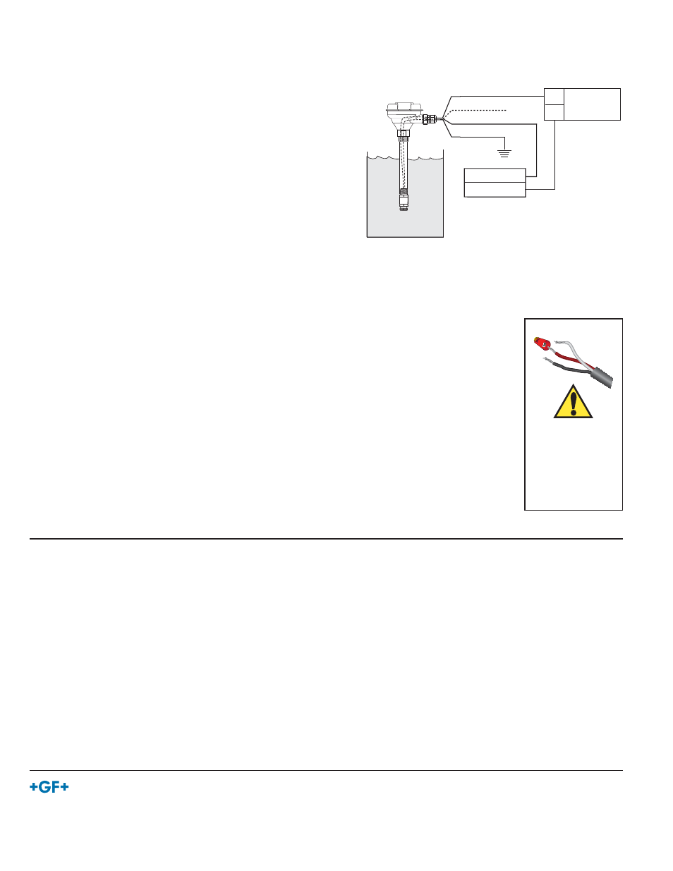
+
-
+
-
3-8052
3-8050.521
4 to 20 mA
loop monitor
Power Supply
DC 12 - 24 V
Black (Loop +)
Red
White (Loop - )
Shield
Optional
Earth Ground
Loop Input
Loop Input
Wire Nut
WARNING!
Keep wire nut on red
wire when not in use.
Failure to protect the
red wire may cause
the 4 to 20 mA span
to be reset.