Digital (s, L) wiring, 4 to 20 ma loop wiring – GF Signet 2450 Pressure Sensor User Manual
Page 3: 4 1/2 inch male union installation, All models of the 2450 provide digital (s, Power supply dc 12 - 24 v, 9900 s, L connector, Cable gland or conduit connection, Loop input
3
2450 Pressure Sensor
3-8052-1
4-20
mA
FREQ/
DA
T
A
WHT
W
HT
BLU
B
LK
N/C
R
ED
SHIELD
SENSOR
INPUT
SHIELD
–
+
FREQ/
DA
T
A
3-8052
3-8900.621C
I/O Module 3-8900.401-X
1
2
3
4
5
6
7
8
9
10
11
12
13
14
+5VDC (Black)
Freq. Input (Red)
GND (Shield)
+5VDC (Black)
Freq. Input 2 (Red)
S L (Red)
GND (White/Shield)
+5VDC (Black)
S L (Red)
GND (White/Shield)
3
3
Analog Output 1
Analog Output 2
(if applicable)
(if applicable)
Frequency
Input
1
Frequency
Input 2
OR
S3L
Input
2
S3L
Input
1
+
-
+
-
GND
V+
IN
DATA
GND
SHLD
V+
White
Black
Red
3-8450
Black
Red
Shield
White
Optional
Earth ground
3-9900
S
3
L connector
3-8900
I/O Module Connector
Black
Red
White
S
3
L connector
Black
Red
White
Shield
The 2450-3X and the 2450-7X sensors have a union-style
process connection. To assemble:
1. Slide union nut onto pipe or fl exible tubing.
2. Install end connectors.
3. Hand-tighten union nut to secure.
Refer to Signet Measurement and Instrumentation Product
Catalogue for ordering information.
Pipe
End Connector
Union Nut
O-Ring
Sensor
not supplied
Cable gland or
conduit connection
3.4 1/2 Inch Male Union Installation
+
-
+
-
3-8052
3-8050.521
4 to 20 mA
loop monitor
Power Supply
DC 12 - 24 V
Black (Loop +)
Red
White (Loop - )
Shield
Optional
Earth Ground
Loop Input
Loop Input
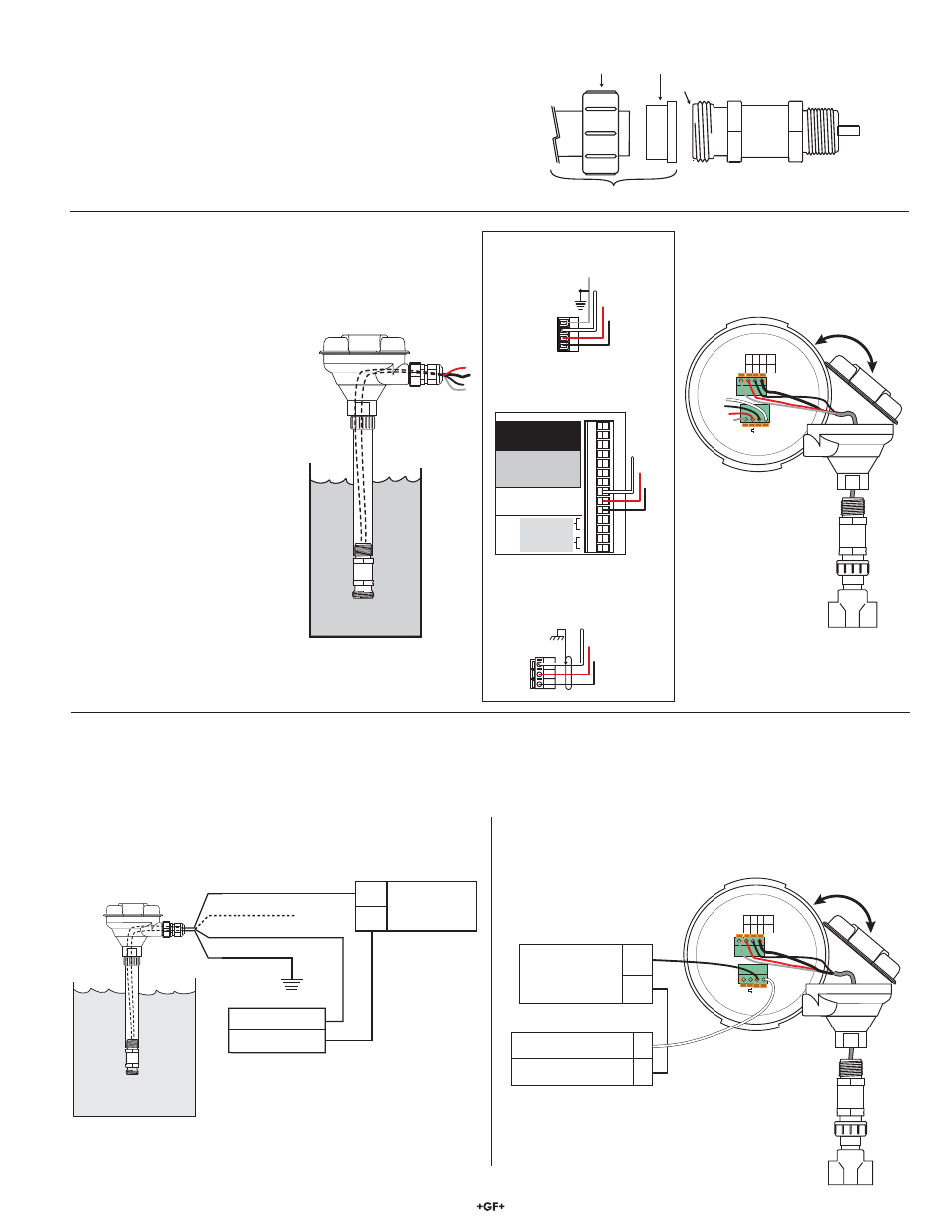
• Connect the 2450 cable directly to a loop device as shown.
4. Digital
(S
3
L) wiring
• All models of the 2450 provide
Digital (S
3
L) output when powered
with 5 VDC.
• Connecting the SHIELD to a direct
earth ground may reduce electrical
noise interference.
• The maximum Digital (S
3
L) cable
length is dependent upon the
instrument to which the sensor
is connected.
Consult the instrument manual for
wiring details.
• Connect the 2450
cable directly to Digital
(S
3
L) I/O terminals.
• When the 2450 includes a
junction box, connect the 2450
terminals to any Digital (S
3
L)
I/O port as shown.
• When the 2450 includes a junction box, connect the 2450
terminals to the loop device as shown.
5. 4 to 20 mA Loop Wiring
• The 2450-7X models provide a 4 to 20 mA loop output when powered with 24 VDC.
• Connecting the SHIELD to a direct Earth ground may reduce electrical noise interference.
• Red wire is not used, do not remove the heat shrink. See Section 6, 4 to 20 mA span adjustment.
5.1 Current Loop With No Junction Box
5.2 Current Loop With Junction Box
3-8052-1
+
-
4-20
mA
FREQ/
DA
T
A
WHT
W
HT
BLU
B
LK
N/C
R
ED
SHIELD
SENSOR
INPUT
SHIELD
–
+
FREQ/
DA
T
A
+
-
White
Black
Power Supply
DC 12 - 24 V
Loop Input
Loop Input