Location of fitting rotor replacement procedure, Sensor mounting position, Standard sensor installation – GF Signet 515 Rotor-X Paddlewheel Flow Sensor User Manual
Page 5: Sensor wiring
5
Signet 515/2536 Rotor-X Flow Sensors
Sensor Installation and Wiring
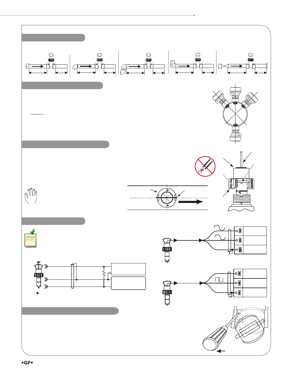
Recommended sensor upstream/downstream mounting requirements.
40x I.D.
5x I.D.
25x I.D.
5x I.D.
50x I.D.
5x I.D.
2 x 90° Elbow
3 dimensions
2 x 90° Elbow
Pump/Valve
15x I.D.
5x I.D.
20x I.D.
5x I.D.
Reducer
90° Elbow
Location of Fitting
Rotor Replacement Procedure
• To remove the rotor, insert a small screwdriver between the rotor and the ear of the sensor.
• Twist the screwdriver blade to fl ex the ear outward enough to remove one end of the rotor and pin.
• DO
NOT
fl ex the ear any more than necessary! If it breaks, the sensor cannot be repaired.
• Install the new rotor by inserting one tip of the pin into the hole,
then fl ex the opposite ear back enough to slip rotor into place.
Process
Pipe
+45°
-45°
0°
Horizontal pipe runs:
• Mount sensor in the upright (0°) position for best performance (pipe must be full).
• Mount at a maximum of 45° when air bubbles are present.
• Do not mount on the bottom of the pipe when sediments are present.
Vertical pipe runs:
• Mount sensor in any orientation.
• Upward
fl ow is preferred to ensure full pipe.
Sensor Mounting Position
sensor
bale
sensor
cap
tab
black
conduit
cap
notch
Figure B
black conduit
cap
PROCESS PIPE
(TOP VIEW)
direction of flow
sensor bale
Figure A
Standard Sensor Installation
Technical Notes
• Use 2-conductor shielded cable for cable extensions.
• Cable shield must be maintained through cable splice.
• Refer to your instrument manual for specifi c wiring details.
Black
Frequency (-)
Red
Frequency (+)
Shield
Ground
515 Sensor Connections to
Signet Instruments
Black
5 VDC
Red
Frequency in
Shield
Ground
2536 Sensor Connections to
Signet Instruments
10 K
+
-
Other Brands
2536 Sensor Connections to Other Brand Instruments
DC sensor power supplied from Signet instrument.
10 K
Pull-up resistor may be required for non-Signet brand instrument.
Input
Gnd.
3.3 to 24
VDC
Black
Shield
Red
Other
instrument
Sensor Wiring
• Lubricate O-rings with a non-petroleum based, viscous lubricant (grease)
compatible with the system.
• Using an alternating/twisting motion, lower the sensor into the fi tting, making sure the
installation arrows on the black cap are pointing in the direction of fl ow, see Figure A.
• Engage one thread of the sensor cap then turn the sensor until the alignment tab is
seated in the fi tting notch.
Hand tighten the sensor cap.
DO NOT use any tools on the sensor
cap or the cap threads and/or fi tting
fl ange threads will be damaged,
see Figure B.