Table of contents dimensions – GF Signet 515 Rotor-X Paddlewheel Flow Sensor User Manual
Page 3
3
Signet 515/2536 Rotor-X Flow Sensors
Table of Contents
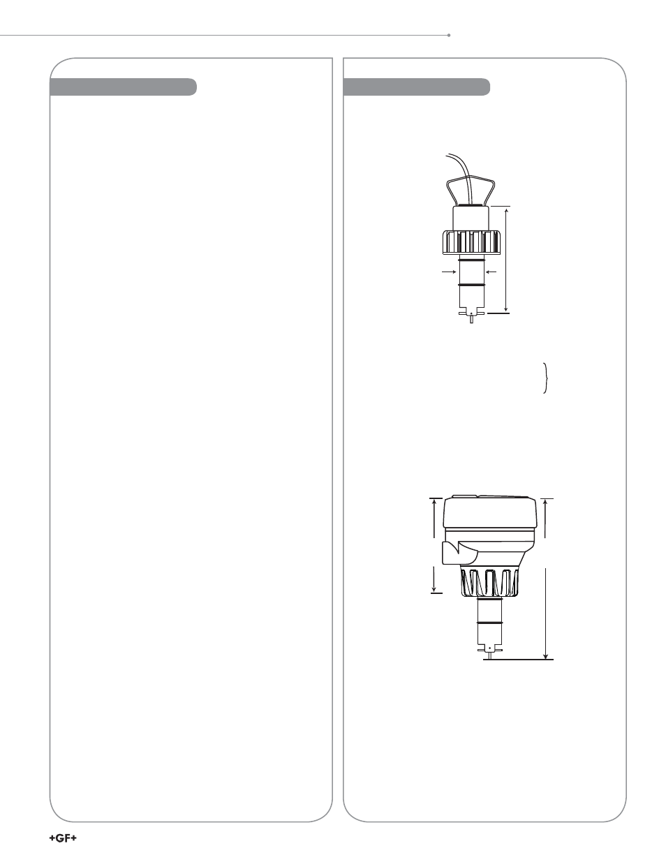
Dimensions
Description............................................................................. 1
Warranty Statement ............................................................... 2
Product Registration .............................................................. 2
Safety Information ................................................................. 2
Chemical Compatibility .......................................................... 2
Table of Contents................................................................... 3
Dimensions ............................................................................ 3
Specifi cations ........................................................................ 4
Location of Fitting .................................................................. 5
Sensor Mounting Position...................................................... 5
Standard Sensor Installation ................................................. 5
Sensor Wiring ........................................................................ 5
Rotor Replacement Procedure .............................................. 5
K-Factors ............................................................................... 6
H-Dimensions ........................................................................ 6
Signet Fittings ........................................................................ 7
Ordering Information (515/8510) ........................................... 7
Ordering Information (2536/8512) ......................................... 8
Table of Contents & Dimensions
102 mm
(4.0 in.)
-X0 or
-X1
-X0 = 152 mm (6.0 in.)
-X1 = 185 mm (7.3 in.)
8510-XX/8512-XX Integral Sensor
shown with Transmitter and
Integral Adapter Kit (sold separately)
Standard
7.6 m (25 ft)
cable
included
26.7 mm
(1.05 in.)
-X (0 thru 5)
Pipe Range:
1/2 in. to 4 in.
-X0 = 104 mm (4.1 in.)
5 in. to 8 in.
-X1 = 137 mm (5.4 in)
10 in. and up
-X2 = 213 mm (8.4 in.)
1/2 in. to 4 in.
-X3 = 297 mm (11.7 in.)
5 in. to 8 in.
-X4 = 332 mm (13.1 in.)
10 in. and up
-X5 = 408 mm (16.1 in.)
Wet-tap
Lengths
1-1/4" NPSM
threaded cap
515/2536 Sensor