Burkert Type 8644 User Manual
Page 82
78 - 8644/phoenix
S
YSTEM
D
ESCRIPTION
In order to adapt the 16-channel digital modules to the data format of the control there is the opportunity to
switch the byte position for channel 1-8 and 9-16. By default, channels 9-16 (slot 3.x and 4.x) are on byte n
and channels 1-8 (slot 1.x and 2.x) are on byte n+1.
The format is switched with bit 4 in the control byte (parameter telegram, byte 11, see
Parameter telegram
section). Channels 1-8 (slot 1.x and 2.x) are then on byte n and channels 9-16 (slot 3.x and 4.x) on byte
n+1.
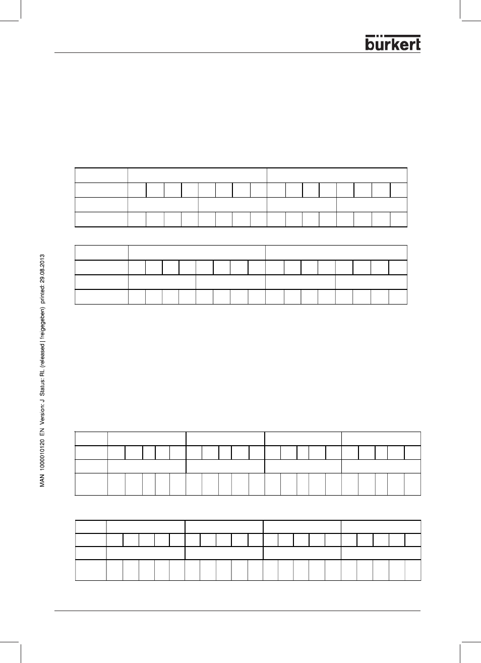
Default (Bit 4=0)
Switched (Bit 4=1)
In order to adapt the 32-channel digital modules to the data format of the control there are opportunities to
switch the byte position of channel groups 1-8, 9-16, 17-24 and 25-32. By default, channel 1-8 (slot 1.x) are
on byte n+3 and channels 9-16 (slot 2.x) on byte n+2, channels 17-24 (slot 3.x) on byte n+1 and channels
25-32 (slot 4.x) on byte n.
If bit 6 is set in the control byte (parameter telegram, byte 11, see
Parameter telegram section), switch the
format. Channels 1-8 (slot 1.x) are then on byte n and channels 9-16 (slot 2.x) on byte n+1, channels 17-24
(slot 3.x) on byte n+2 and channels 25-32 (plug 4.x) on byte n+3.
Default (Bit 6=0)
Switched (Bit 6=1)
Byte
0
1
Bit
7
6
5
4
3
2
1
0
7
6
5
4
3
2
1
0
Slot
4
3
2
1
Terminal point 2.4
1.4
2.1 1.1
2.4 1.4
2.1
1.1
2.4
1.4
2.1 1.1
2.4 1.4
2.1
1.1
Byte
1
0
Bit
7
6
5
4
3
2
1
0
7
6
5
4
3
2
1
0
Slot
4
3
2
1
Terminal point
2.4 1.4
2.1 1.1
2.4
1.4
2.1
1.1
2.4
1.4
2.1 1.1
2.4
1.4
2.1
1.1
Switching round bytes in IB IL24 DI16 / IB IL24 DO16 terminals
Switching round bytes on IB IL24 DI32 / IB IL24 DO32 terminals
Byte
0
1
2
3
Bit
7
6
...
1
0
7
6
...
1
0
7
6
... 1
0
7
6
...
1
0
Slot
4
3
2
1
Terminal
point
8.4
7.4
...
8.-
1
7.1
6.4
5.4
...
6.1
5.1
4.4 3.4
...
4.1
3.1 2.4
1.4
...
2.1
1.1
Byte
0
1
2
3
Bit
7
6
...
1
0
7
6
...
1
0
7
6
...
1
0
7
6
...
1
0
Slot
1
2
3
4
Terminal
point
2.4
1.4
...
2.1 1.1
4.4 3.4
...
4.1
3.1 6.4 5.4
...
6.1
5.1
8.4
7.4
...
8.1
7.1