Orifice sizing -12, 5 application configuration -12, 6 orifice sizing – Brooks Instrument 5866M User Manual
Page 35
Brooks Instrument Model 5866 Pressure Controller
5-12
9. If the flow shuts off, or is less than the maximum allowable leak through
for the type of valve seat installed the adjustment is complete.
10.If the leakage at 18 Volts is excessive add a large 0.005" spacer (10) to
decrease the air gap and repeat Steps 8 and 9.
5-6 Orifice Sizing
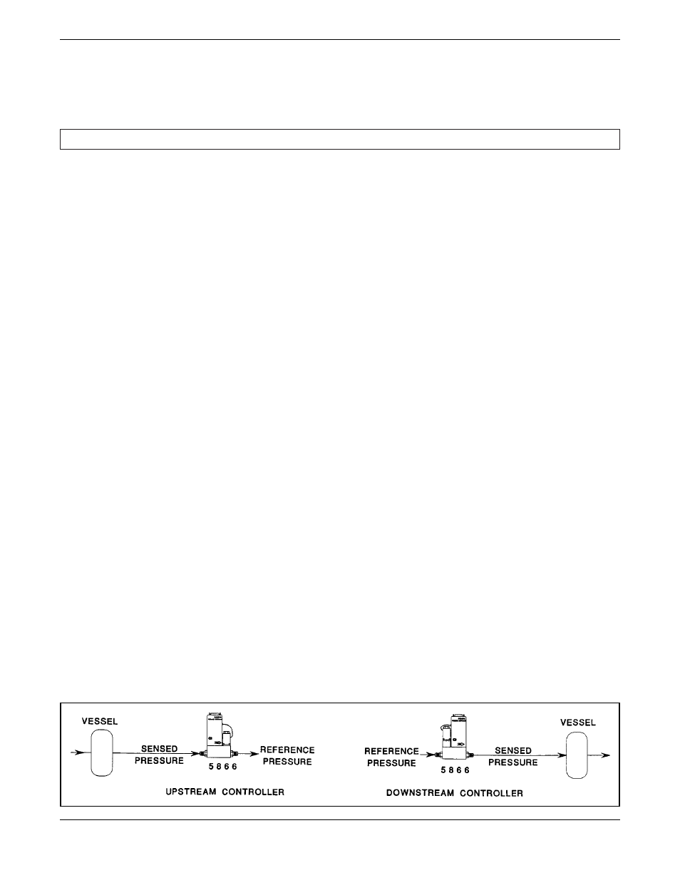
The Model 5866 Pressure Controller can be configured with the valve on
the outlet to control the pressure upstream of the instrument. This
configuration is called an upstream controller. The Model 5866 can also be
configured with the valve on the inlet to control the pressure downstream
of the instrument. This configuration is called a downstream controller.
The calibration or sensed pressure is the pressure that is controlled. This
is the upstream pressure for an upstream controller or downstream
pressure for a downstream controller. The reference pressure is the
pressure opposite the calibration pressure. The reference pressure would
be the downstream pressure for an upstream controller and the upstream
pressure for a downstream controller. The reference pressure is usually
relatively constant. The calibration pressure is the pressure to which the
electronics is calibrated to give 100% output signal. The calibration
pressure is the maximum sensed pressure. The above definitions are
shown in Figure 5-5.
To properly size the control valve orifice in the Model 5866 the following
information must be known:
· Calibration Pressure, psia
· Reference Pressure, psia
· T
=
Gas Temperature (approximate) °R, (°R = °F + 460)
· Q
max
=
Max. Flow, sccm, 0°C reference temperature
· SG
=
Gas Specific Gravity, reference Air @ 14.7 psia and
70°F=1.0
1. Determine the minimum pressure drop across the pressure controller.
·
For an upstream controller this will be when the sensed (inlet) pressure
is 5% of the calibration pressure, or 1.5 psi, whichever is larger.
·
For a downstream controller this will be the reference pressure minus
the calibration pressure.
2. Determine the P1 and P2 in psia.
·
For an upstream controller P1 is the reference pressure plus the
minimum pressure drop. P2 is the reference pressure.
P1=P
Ref
+ minimum pressure drop
P2=P
Ref
Figure 5-5. Application Configuration.
P1
CALIBRATION
OR
P2
P1
P2
CALIBRATION
OR