1 d-connector pin arrangement -5, Ansducer signal (refer to section 2-11), Table 2-1 – Brooks Instrument 5866M User Manual
Page 16: 9 valve override, 10 precision 5v reference, 11 remote transducer input, 12 valve test point
2-5
Installation
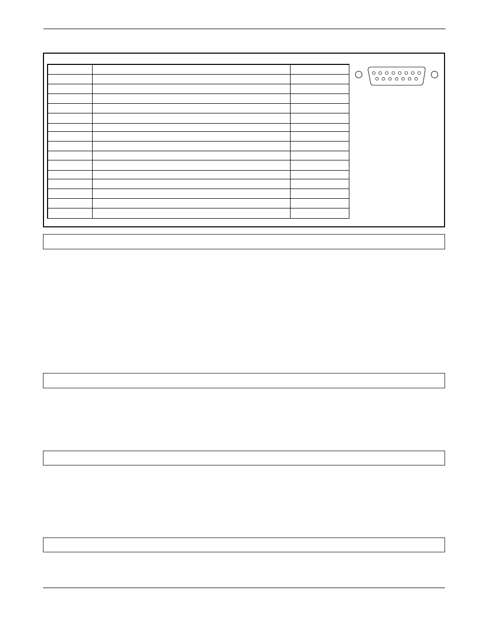
Table 2-1. D-Connector Pin Arrangement.
PIN NO.
FUNCTION
COLOR CODE
1
Command Common (Command Pot "CCW")
Black
2
Voltage Signal Output
White
3
Remote Valve Return
Red
4
Current Output
Green
5
+15 Vdc Supply
Orange
6
-15 Vdc Supply
Blue
7
Valve Voltage Out/External Valve Control
Wht/Blk
8
Command Input (Command Pot "S")
Red/Blk
9
Supply Voltage Common
Grn/Blk
10
Voltage Signal Common
Org/Blk
11
+5 Volt Reference (Command Pot "CW")
Blu/Blk
12
Valve Override
Blk/Wht
13
+15 Vdc Supply (1)
Red/Wht
14
Chassis Ground (2)
Grn/Wht
15
External Sensor Input
Blu/Wht
NOTES:
1. Pin 13 does not have to be
connected if current I/O is
not used.
2. Cable shield tied to chassis
ground in meter connector.
1
15
9
8
2-9 Valve Override
The valve override function allows full opening and closing of the valve
independent of the command setting.
The valve override for the pressure controller is as follows:
a. To open the valve, apply +15 Vdc to the valve override terminal.
b. To close the valve, apply -15 Vdc to the valve override terminal.
The valve override function is accessed from Terminal 12 (refer to Figure
2-1 and Table 2-1).
Note: For normal operation, Terminal 12 may be left open (floating) or
grounded.
2-10 Precision 5V Reference
The Model 5866 is equipped with a precision 5 Vdc reference. The
reference is used internally for precise zero adjustment and is also
available as a buffered output for use in conjunction with a 1 to 10 k ohm
potentiometer to provide 0-5 Vdc set-point. The 5 Vdc reference is
available at Terminal 11 (refer to Figure 2-1 and Table 2-1).
2-11 Remote Transducer Input
To allow the Model 5866 control circuitry and valve to be used with an
external transducer signal such as a capacitance manometer, Jumper J2
“C” or “D” must be moved to the Position B. Jumper J2, "A" can be in either
Position a or b depending on valve/controller type. The external sensor
signal (0-5 or 0-10 Vdc) must be connected to Terminals 15 and 10 (refer
to Figure 2-1 and Table 2-1).
2-12 Valve Test Point
The valve voltage may be monitored on Terminal 7 of the D-Connector.