Table 5-2), En in table 5-2. if an, 3 troubleshooting table 5-1. bench troubleshooting – Brooks Instrument 5866M User Manual
Page 26: Table 5-2. sensor troubleshooting
5-3
Troubleshooting
Table 5-1. Bench Troubleshooting.
Trouble
Possible Cause
Check/Corrective Action
Output stays at zero Volts regardless of com- Defective Sensor
Replace sensor. Refer to Section 5-3 and Table 5-2.
mand and there is pressure on the controller.
Output stays at zero Volts regardless of
Clogged Control Valve
Check Pin 7 if the voltage is more than +11 V. Disassemble and repair the control valve.
command and there is no flow through the
Refer to Sections 5-3 and 5-4.
controller.
-15 V applied to the valve override input.
Check valve override input. Refer to Figure 2-2 for terminal assignments.
Defective printed circuit board.
Replace printed circuit board. Refer to Sections 5-3 and 5-4.
Output signal stays at +14 V. regardless of
Valve stuck open or leaky.
Clean and/or adjust control valve. Refer to cleaning procedure and/or Section 5-5.
command and there is flow through the
controller.
+15 Vdc applied to the valve override input.
Check the valve override terminal. Refer to Figure 2-2 for terminal assignments.
Defective printed circuit board
Replace printed circuit board. Refer to Sections 5-3 and 5-4.
Command input floating.
Connect command signal. Refer to Figures 2-1 and 2-2 for terminal assignments.
Output signal follows setpoint at higher
Leaky control valve.
Disassemble and repair valve. Refer to Sections 5-3 and 5-4.
commands but will not go to zero.
Excessive resistance in valve voltage return
Reduce wiring resistance
line.
Output signal follows setpoint at lower
Insufficient inlet pressure or pressure drop
Adjust pressures, check calibration. Refer to Section 5-1.
commands but does not reach full scale.
Partially clogged valve.
Disassemble and repair control valve. Refer to Sections 5-3 and 5-4.
Valve out of adjustment.
Adjust valve. Refer to Section 5-5.
Valve guide spring failure.
Controller oscillates (see below)
Controller oscillates.
Pressure drop or inlet pressure excessive.
Adjust pressures.
Oversized orifice
Check orifice size. Refer to Section 5-6 and Table 5-4.
Valve out of adjustment.
Adjust valve. Refer to Section 5-5.
P/I adjustment not correct.
Adjust P/I potentiometers. Refer to Section 3-2.
Faulty pressure regulator.
Check regulator output.
Defective printed circuit board
Replace printed circuit board. Refer to Sections 5-3 and 5-4.
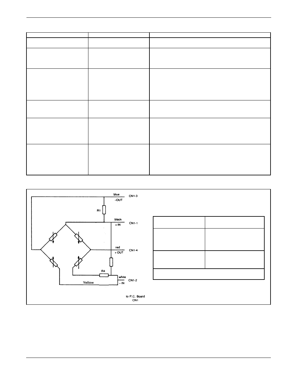
Table 5-2. Sensor Troubleshooting.
OHMMETER
RESULT IF ELECTRICALLY
CONNECTION
FUNCTIONAL
4 Sensor wires to body
Open circuit on Ohmmeter.
(ground)
If one of these is shorted,
(Pin 1 to 4 to body)
an Ohmmeter reading will
be obtained.
Between the different
Minimum 1 k Ohm
wires
Maximum 4 k Ohm
Depending on sensor used
NOTE: Remove the sensor connector from the P.C. board
for this procedure.