2 adjustment test setup -7, Caution – Brooks Instrument 5866M User Manual
Page 30
5-7
Troubleshooting
The valve is adjusted in Brooks pressure controllers by adding spacers (9
and 10) to the control valve to vary the initial position of the parts. The
proper initial position is required so the valve will have the proper travel
and force available to insure reliable control. Screw type adjustments are
not used in Brooks control valve since they can change with pressure and
vibration. Screw type adjustments also introduce a dynamic seal that is a
potential leak site and source for contamination.
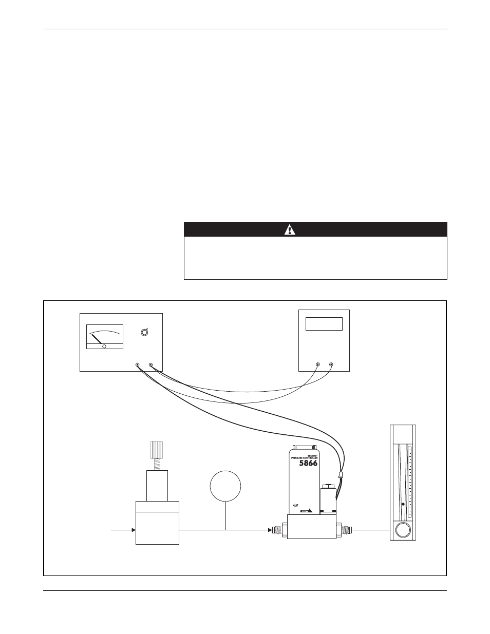
The adjustment procedures below require the use of a variable voltage
power supply, pressure regulator, pressure gage, voltmeter, flow meter and
a supply of nitrogen or air. The test set up is shown in Figure 5-2. The
power supply must be capable of delivering 400 mA at 30 V. If the proper
equipment or facilities are not available to perform this procedure, please
return the instrument to the factory or an authorized repair station. Refer to
Figure 7-1 for the location of the parts. Section A describes the adjustment
of the Normally Closed control valve, Section B describes the adjustment
of the Normally Open control valve. Please refer to the proper section for
your valve type.
When testing upstream type pressure controllers, be certain not to
exceed the maximum overpressure specification for the pressure
transducer installed, as specified in Section 1-4. For the 0-1 bar
transducer this is only 7 psig!
CAUTION
Figure 5-2. Adjustment Test Setup.
®
Model 5866
Pressure
Regulator
Pressure
Gage
Variable
Power Supply
Nitrogen
or Air
Voltmeter
Flow Meter
P
+
-
+
-