Part 4 - software utilities – Dynasonics MFX Series Insertion MagProbe Flow Meter User Manual
Page 58
Rev. 01/11
-4.6-
MFX
3. ADVANCED TAB - does not pertain to MFX
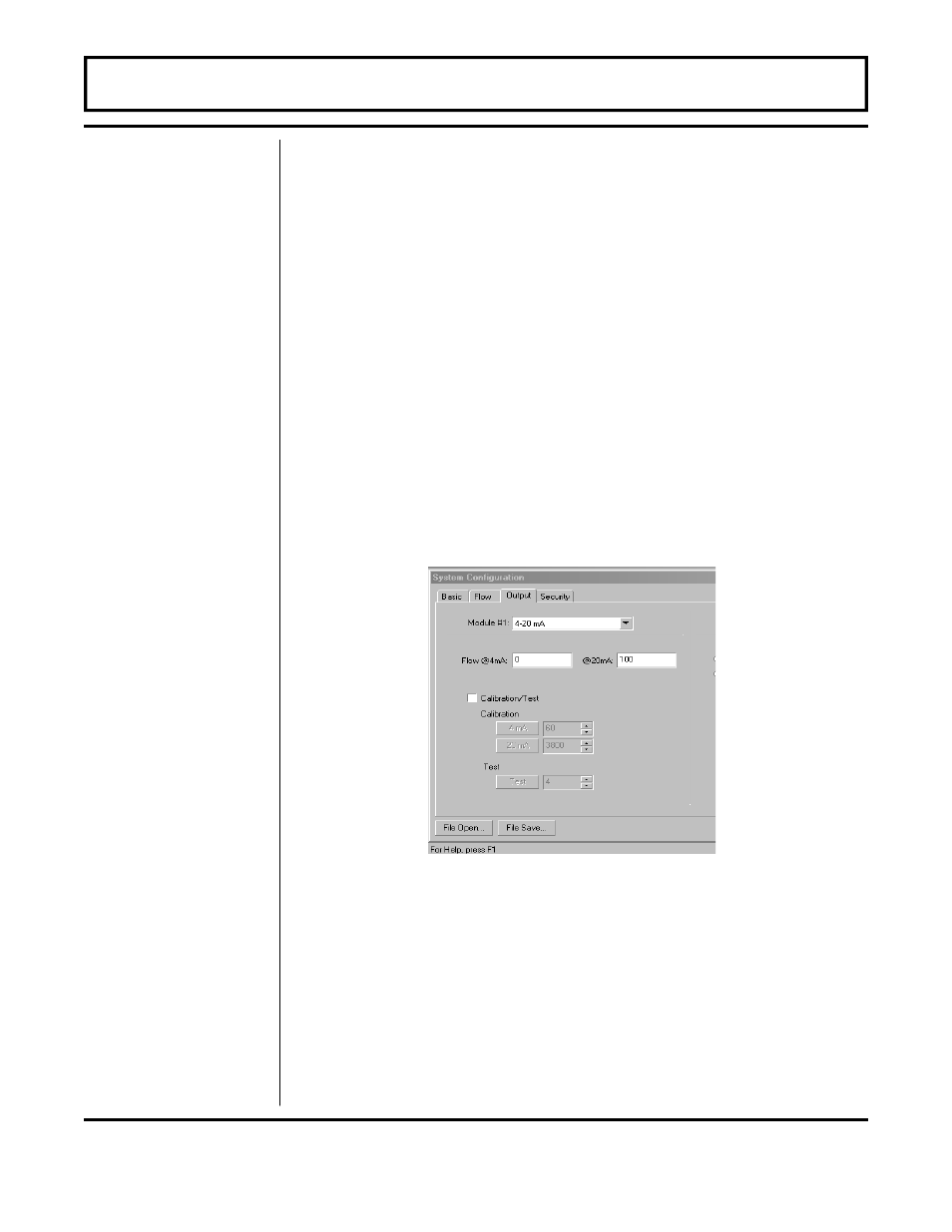
4. OUTPUT TAB - see Figure 4.4
The entries made in the Output tab establish input and output
calibration and ranges for the ISO-MOD module installed in the
MFX flow meter. If an optional module was ordered from and
installed at the Dynasonics factory, the Output tab will contain
information and configuration for that module. If a module is to be
installed in the field, place the module into the Module #1 position
and secure with screws. Select the appropriate module from the pull
-down menu and press the Download button. If a module has been
changed from the factory setting, a Configuration error will result.
This error will be cleared by resetting the MFX microprocessor
from the Communications/Commands/Reset Target button or by
cycling power on the MFX flow meter. Once the proper output
modules are selected and the microprocessor is reset, calibration
and configuration of the modules can be completed. If a module slot is
empty in the MFX enclosure, select NONE as the module type.
PART 4 - SOFTWARE UTILITIES
Output
Configuration
Figure 4.4
Output Tab