Part 2 - magprobe installation – Dynasonics MFX Series Insertion MagProbe Flow Meter User Manual
Page 33
Rev. 01/11
-2.8-
MFX
MAGPROBE INSERTION DMP2 through DMP6
1. Apply sealant to the 1-½" NPT threads of the insertion fitting
assembly. Screw the assembly into the isolation valve and
tighten with a 2-½" pump wrench. Final orientation of the two
threaded rods on the MagProbe insertion fitting should be
approximately perpendicular to the pipe’s axis.
2. Run the lower Jam Nuts down to a point that approximates the
final insertion position or at least far enough to allow insertion of
the MagProbe into the insertion Fitting. Using the threaded rods
as a guide and with the flow direction arrow pointing in the
correct direction, position the MagProbe in the insertion fitting.
Continue to insert the MagProbe as far into the isolation
assembly as possible. The MagProbe tip will come in contact
with the closed “ball” in the isolation valve.
CAUTION: Do Not Force the MagProbe Tip Against the “Ball”, as
damage to the MagProbe tip may result.
3. Replace the upper Jam Nuts (2 on each rod) and the cotter pins.
The nuts should be run down to the top side of the retaining
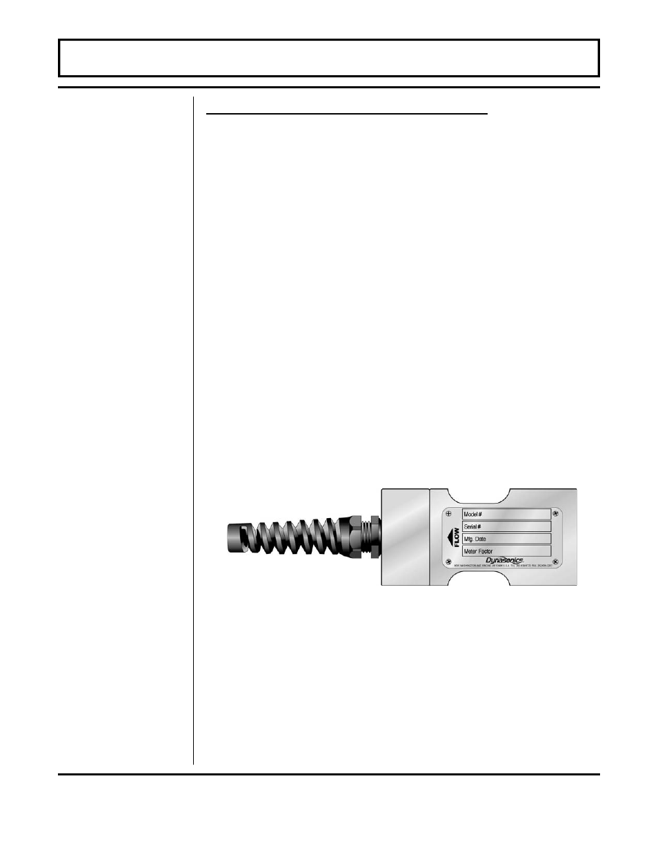
collar and the cotter pins replaced. Orient the MagProbe in the
direction of flow as indicated on by the FLOW direction arrow
located on the top of the MagProbe amplifier enclosure. See
Figure 2.6.
CAUTION: The nuts on both ends of the retaining rods must
always be in place as a safety measure to prevent possible
MagProbe blow out. Inserting cotter pins is a further safety
measure.
PART 2 - MAGPROBE INSTALLATION
Step F -
MagProbe
Insertion DMP2
through DMP6
Figure 2.6
Flow Direction