Part 1 - transmitter installation – Dynasonics MFX Series Insertion MagProbe Flow Meter User Manual
Page 16
Rev. 01/11
-1.14-
MFX
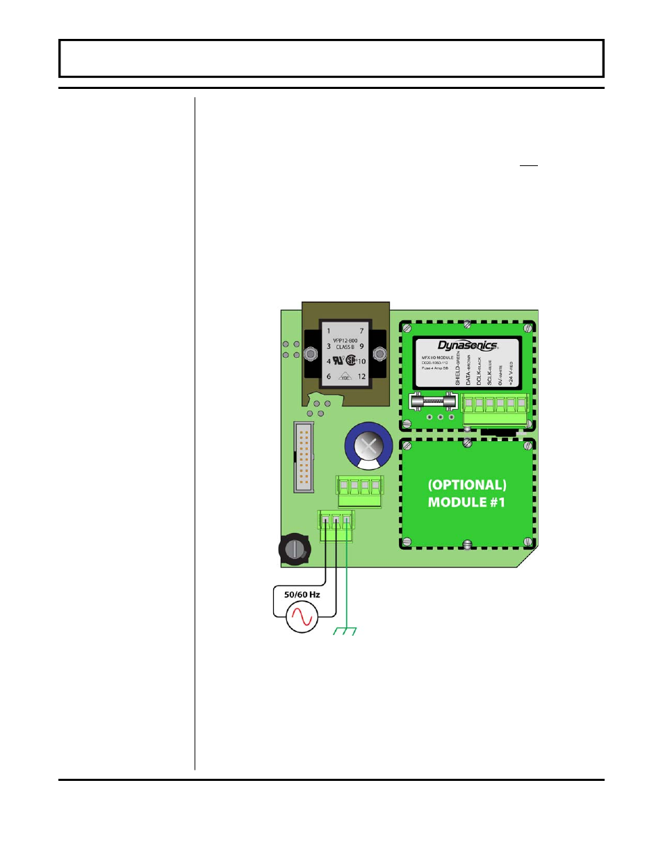
AC POWER CONNECTIONS
1. Verify that the jumpers at JP3 are properly oriented for the power
supply. Verify that the jumpers at JP1 and JP2 are not present.
2. Connect L1, L2 and earth to the terminals referenced in Figure
1.7 on page 1.13. Phase and neutral connections to L1 and L2 are
not polarized. Do not operate without an earth ground
connection.
3. See Figure 1.8 for AC connection schematic. Wire gauges up to
14 AWG can be accommodated in the MFX terminal blocks.
PART 1 - TRANSMITTER INSTALLATION
Figure 1.8
AC Power Connection