Part 1 - transmitter installation – Dynasonics MFX Series Insertion MagProbe Flow Meter User Manual
Page 17
Rev. 01/11
-1.15-
MFX
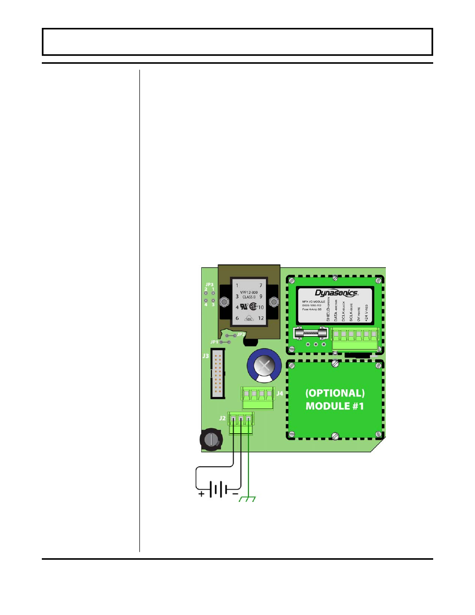
DC POWER CONNECTIONS
The MFX may be operated from a 9-28 Vdc source, as long as the
source is capable of supplying a minimum of 3 Watts.
1. Verify that the jumpers are properly placed. See the wiring
diagram located on the inside door of the MFX enclosure or see
Figure 1.7 on page 1.13. The jumpers at JP3 should not be
present and the jumpers at JP1 and JP2 will be in place. The
jumper located beneath the microprocessor protection shield—
the panel with the wiring diagram label mounted on it—should be
positioned at JP2 for 9-16 Vdc input power and in JP1 position
for 16-28 Vdc input power.
2. Connect the DC power source as illustrated in the schematic in
Figure 1.9. Wire up to 14 AWG can be accommodated in the
MFX terminal blocks.
PART 1 - TRANSMITTER INSTALLATION
DC Power
Supply
Figure 1.9
DC Power Connection