Part 1 - transmitter installation, Figure 1.7 mfx power supply configuration, Wiring diagram – Dynasonics MFX Series Insertion MagProbe Flow Meter User Manual
Page 15: Jp1/jp2, Caution, Connections
Rev. 01/11
-1.13-
MFX
CAUTION: Any other wiring method may be unsafe or cause
improper operation of the instrument.
Do not run line power with other signal wires within the same wiring
tray or conduit.
NOTE: This instrument requires clean electrical line power. Do not
operate this unit on circuits with noisy components (i.e. fluorescent
lights, relays, compressors, variable frequency drives, etc.)
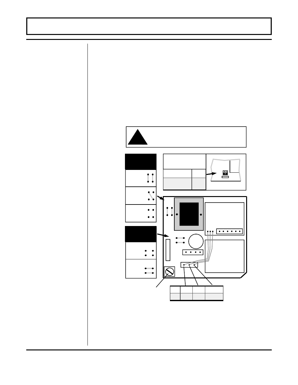
PART 1 - TRANSMITTER INSTALLATION
Figure 1.7
MFX Power Supply Configuration
JP2
WIRING DIAGRAM
J2
J4
No Connections
Optional
I/O Module
Fuse (5x20mm):
AC: 0.1A/250V Delay
DC: 0.5A/250V Delay
JP3
J3
AC
L1
L2
EARTH
DC
+V
GND
EARTH
1
2
3
4
1
2
1
2
JP1
115 Vac
230 Vac
JP3
Connections
9-28 Vdc
1
2
3
4
1
2
3
4
1
2
3
4
115/230
Vac
JP1/JP2
Connections
9-28 Vdc
1
2
1
2
1
2
1
2
CAUTION!
To avoid serious injury or
product damage, disconnect electrical power
before servicing this meter.
!
16-28 Vdc
JP1
9-16 Vdc
115/230 Vac
JP2
12 or 24 Vdc jumper
selection located on the
circuit board below this
decal.
Bottom of circuit board
Y1
JP1
R41
JP2
GREEN/SHIE
LD
BR
O
W
N
BLAC
K
BLU
E
WH
IT
E
RE
D
MagProbe
Interface Module
D003-0905-301 REV. B
L1
L2
EAR
TH