Part 2 - magprobe installation – Dynasonics MFX Series Insertion MagProbe Flow Meter User Manual
Page 32
Rev. 01/11
-2.7-
MFX
PROBE CABLE
Before inserting the MagProbe into the pipe, the sensor cables
should be routed to the transmitter location. Locate the transmitter
within the length of MagProbe cable that was supplied with the MFX
system. If this is not possible, replace the entire length of
interconnect cable with Belden
®
part number 9536, Dynasonics part
number D005-1003-003 or equivalent. Do not splice the cable as
shield integrity will be compromised and poor performance can
result. Cable lengths up to 1000 feet (300 meters) can be utilized.
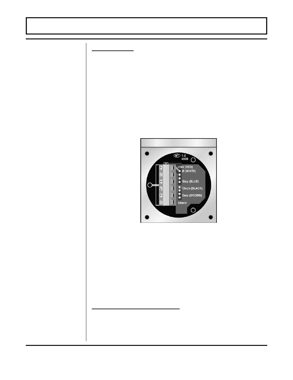
The wiring inside of the MagProbe conduit box is pictured in
Figures 2.5.
CAUTION: Both power and digital signals are carried through the
MagProbe cable. These signals are robust, but care should be
taken in routing the cables. Avoid running cables near sources of
high voltage equipment or sources of extreme electrical noise—high
EMI/RFI. Also avoid routing the cables in cable tray configurations,
unless the trays are specifically used for other low voltage, low level,
signal cables.
PROBE GROUND CONNECTION
Attach a wire of 12 AWG or larger between the #10-32 ground lug
on the insertion fitting and earth ground.
Step E -
Cable Routing
PART 2 - MAGPROBE INSTALLATION
IMPORTANT
NOTE!
Figure 2.5
MagProbe Interface Enclosure