Part 3 - keypad configuration, Flow rate relay error alarm relay – Dynasonics MFX Series Insertion MagProbe Flow Meter User Manual
Page 46
Rev. 01/11
-3.12-
MFX
For example, if the Totalizer Exponent is set to E0 (
1) and the
Relay Multiplier is set to 1, then the relay will pulse each time the
totalizer increments one count, or each single, whole measurement
unit totalized.
If the Totalizer Exponent is set to E2 (
100) and the Relay
Multiplier is set to 1, then the relay will pulse each time the display
totalizer increments or once per 100 measurement units totalized.
If the Totalizer Exponent is set to E0 (
1) and the Relay Multiplier
is set to 2, the relay will pulse once for every two counts that the
totalizer increments.
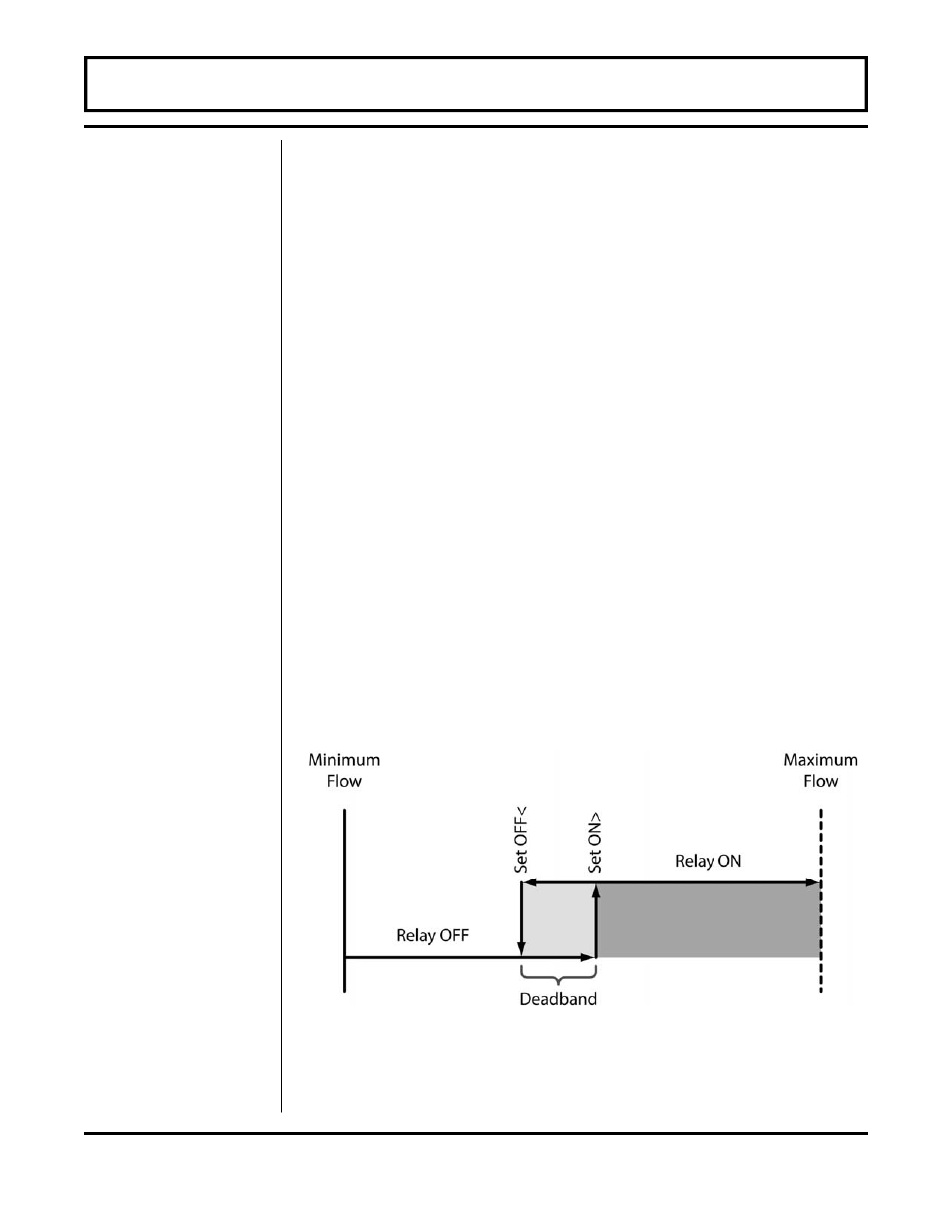
Flow Rate Relay configuration permits relay changeover at two
separate flow rates allowing operation with an adjustable switch
deadband. Figure 3.1 illustrates how the setting of the two set
points influences rate alarm operation.
A single-point flow rate alarm would place the ON> setting slightly
higher than the OFF< setting—allowing a switch deadband to be
established. If a deadband is not established, switch chatter (rapid
switching) may result if the flow rate is very close to the switch point.
When a relay is set to ERROR mode, the relay will activate when
any error occurs in the flow meter that has caused the meter to stop
measuring reliably. See the Appendix of this manual for a list of
potential error codes.
PART 3 - KEYPAD CONFIGURATION
Flow Rate
Relay
Error Alarm
Relay
Figure 3.1
Single Point Alarm Operation