Reserve control input (cc2), Pixel order, Reserve control input (cc2) pixel order – ALLIED Vision Technologies Bonito CL-400 200 fps User Manual
Page 33
Camera Link interface (01-04 or CL1, CL2)
Bonito Technical Manual V2.3.0
33
Reserve control input (CC2)
The camera control signals CC2 at the Camera Link connectors O2 and O4 (or
connector CL1) are reserved for future use.
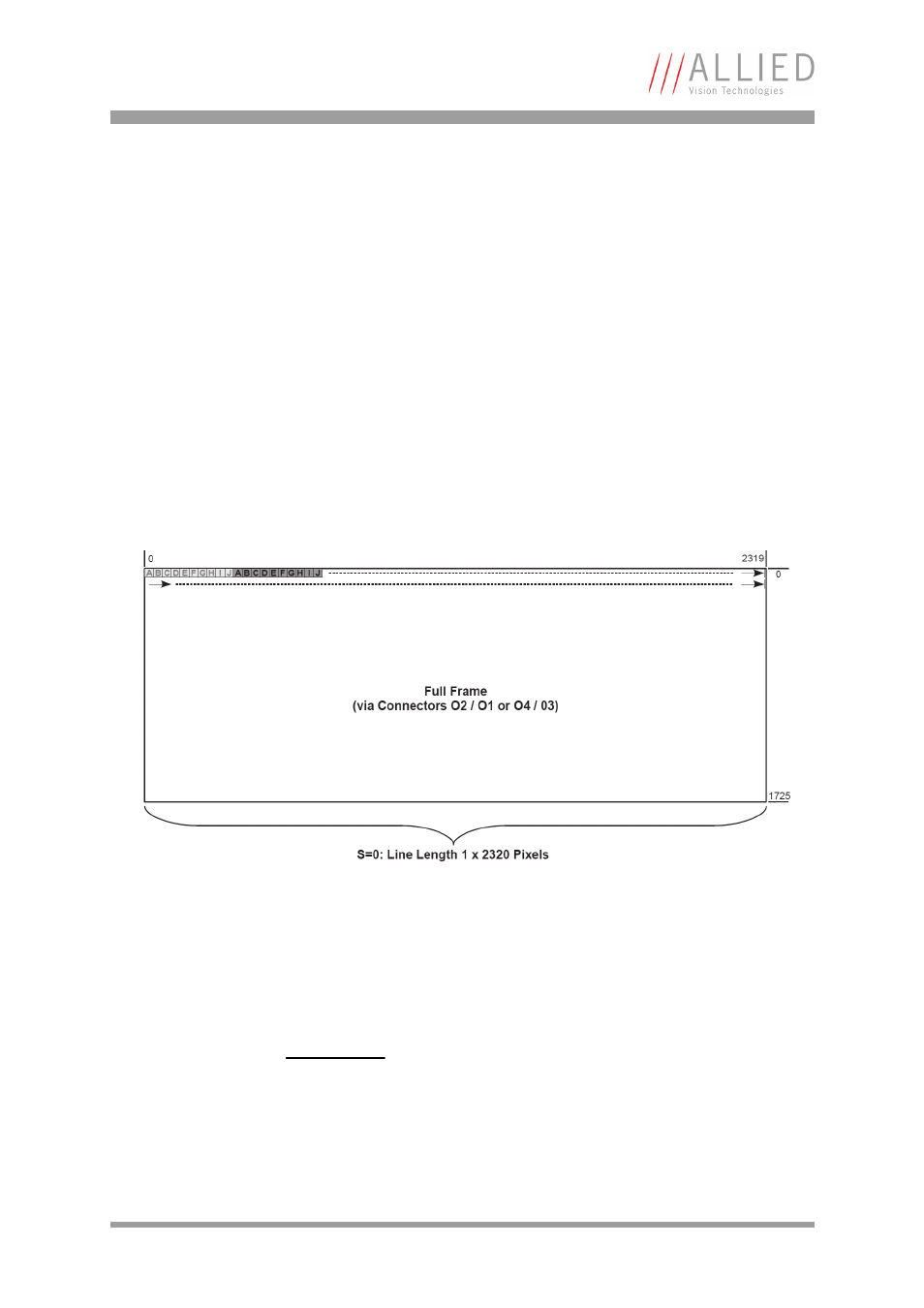
Pixel order
Each frame in single channel mode (
S=0, max. 193 full frames per second) is
transmitted from top left to bottom right, line per line. The diagram below
shows how the image is reconstructed from the ten Camera Link taps A – J.
Because every tap directly corresponds to a Camera Link port, the port labels are
reused as tap labels here. Each Camera Link clock cycle transmits one block of
ten pixels. Note that the number of lines may vary depending on the value of
parameter
N
.
In the high-speed dual channel modes (
S=1
or
S=3
, max. 386 full frames per
second) the image is split up vertically into two equal sized halves. Each half
uses its own Camera Link channel and the pixel data travels over the corre-
sponding connector pair.
Figure 15: Pixel order: full frame
Note
This mode is not available for the Bonito CL-400B/C 200fps
cameras.