7 wiring power and switches to drive, Wiring power and switches to drive – DE-STA-CO IM-pAC AC Drive Getting Started Guide User Manual
Page 7
IM-pAC Getting Started Guide
7
Issue Number: 5
www.camcoindex.com | www.destaco.com
Re
a
Sa
R
Me
ch
Ele
n
Ke
Par
D
UL
Li
1.6
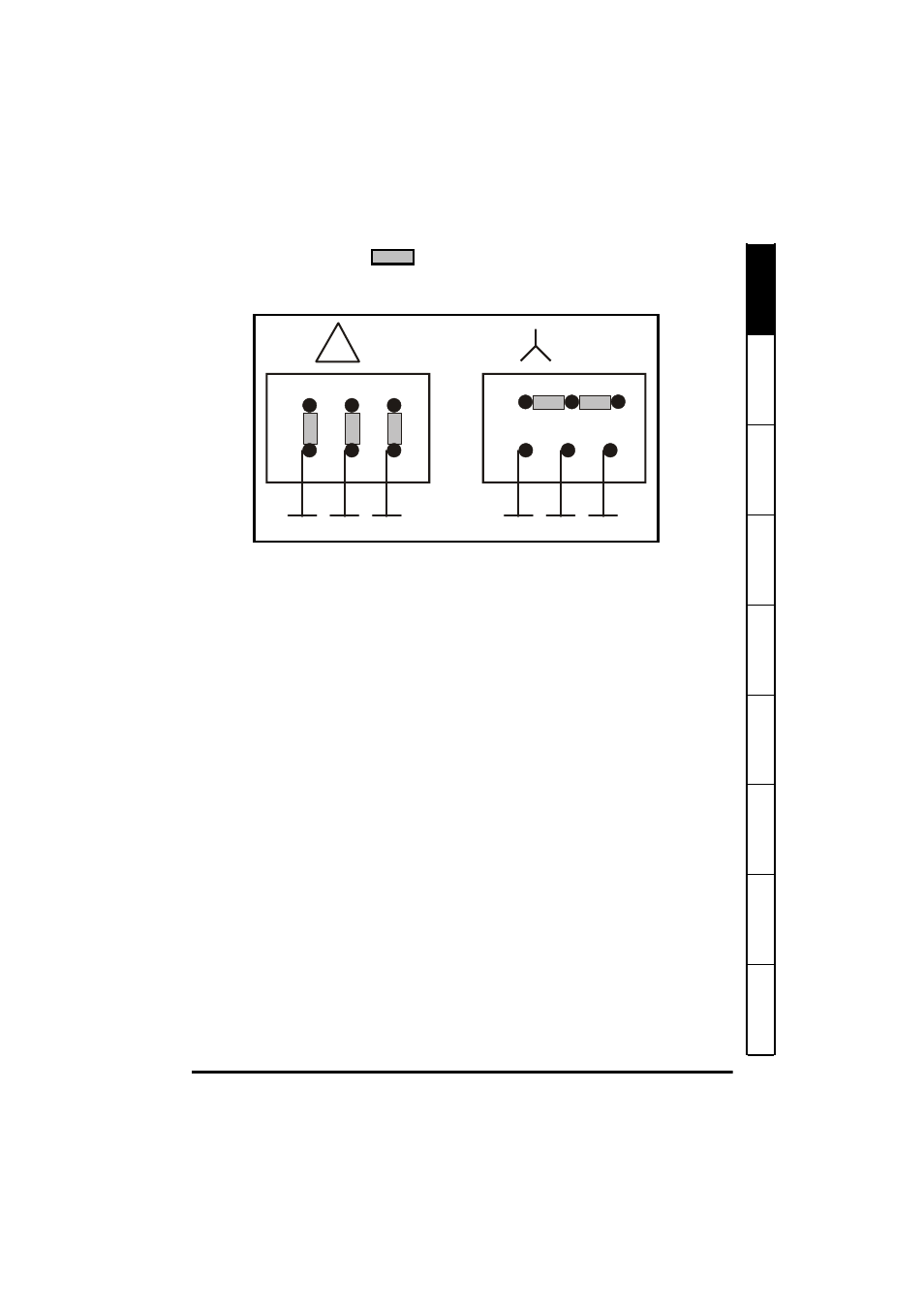
Motor Jumper
Configuration for 1/3 hp and 1.00 hp
motors
1.7
Wiring Power and Switches to Drive
1. Refer to Chapter 3 Rating Data for all other fuse sizes and control and motor cable
wire sizes. Single phase can be obtained from a 3 phase "wye" by wiring two of the
"hots" (L1 and L2 or L2 and L3 or L1 and L3) to the drive. Do not remove internal
EMC filter. See Chapter 5.
2. The control terminal B2 outputs 24 volts DC and will be used to power the signals.
The control terminal B4 is used to enable the drive. As long as B2 and B4 are
connected the drive will run. Use a normally closed switch (not supplied by IMC) or
jumper between B2 and B4 to enable the drive. The control terminal B5 runs the
motor forward and B6 runs the motor in reverse. If the indexer is not turning in the
proper direction interchange B5 and B6.
3. Make sure the indexer is in the middle of its dwell position before starting or
stopping the motor. see section 1.16 Indexer drive shown in middle of dwell
position diagram.
4. The motor is made to run by closing the B2-B5 or B2-B6 terminals. Opening them
will stop the motor.
5. Cycling on demand using a limit switch and inverter duty motor. The normally closed
side of the cam shaft limit switch should be wired to terminals B2 and B5 (or B6).
When the indexer is in dwell the switch will be open. A start signal is sent by
momentarily closing B2 and B5 with an external switch. As the camshaft is turning
the limit switch on the cam shaft will close and thus maintain the B2-B5 (or B6)
closure. When the indexer enters dwell the trip cam on the cam shaft will cause the
limit switch to open the B2-B5 (or B6) connection and stop the motor.
Diagram for wiring switches to the IM-pAC control terminals (cover has been removed)
for cycling on demand using a limit
switch, momentary start and inverter duty motor.
Index drive is in middle of dwell position see section 1.16 Indexer drive shown in middle
of dwell position diagram.
W2 U2
V2
U1
V1
W1
230V
W2 U2
V2
U1
V1
W1
400-460V
L1
L2
L3
L1
L2
L3