DE-STA-CO IM-pAC AC Drive Getting Started Guide User Manual
Page 55
IM-pAC Getting Started Guide
55
Issue Number: 5
www.camcoindex.com | www.destaco.com
Re
Sa
R
Me
ch
El
Pa
ram
D
UL
Li
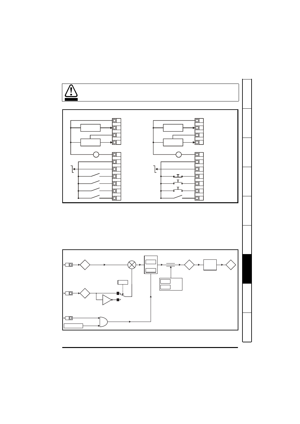
Figure 7-8 Pr 05 = Pid
When Pr 05 is set to Pid, the following parameters are made available for adjustment:
•
Pr 61: PID proportional gain
•
Pr 62: PID integral gain
•
Pr 63: PID feedback invert
•
Pr 64: PID high limit (%)
•
Pr 65: PID low limit (%)
•
Pr 66: PID output (%)
Figure 7-9 PID logic diagram
When torque mode is selected and the drive is connected to an unloaded motor, the
motor speed may increase rapidly to the maximum speed (Pr 02 +20%)
WARNING
0V
+10V reference output
+24V output
Drive Enable/Reset
Run Forward
Run Reverse
4-20mA PID
feedback input
V
_
+
+24V
0V
Eur
USA
Analog output
(motor speed)
Digital output
(zero speed)
PID feedback input
PID reference input
PID enable
0-10V PID
reference input
0V
+10V reference output
+24V output
/Stop
Run
Jog
4-20mA PID
feedback input
V
_
+
+24V
0V
Analog output
(motor speed)
Digital output
(zero speed)
PID reference input
PID enable
0-10V PID
reference input
PID feedback input
T1
T2
T3
T4
B1
B2
B3
B4
B5
B6
B7
T1
T2
T3
T4
B1
B2
B3
B4
B5
B6
B7
95
94
%
T4
T2
x(-1)
0
1
63
Invert
61
P Gain
62
I Gain
PID reference
input
%
PID feedback
input
B7
PID enable
&
Drive healthy
64
PID high
limit
65
PID low
limit
66
%
81
Drive
reference
Hz
% to
frequency
conversion
+
_