DE-STA-CO IM-pAC AC Drive Getting Started Guide User Manual
Page 61
IM-pAC Getting Started Guide
61
Issue Number: 5
www.camcoindex.com | www.destaco.com
Re
Sa
R
Me
ch
El
Pa
ram
D
UL
Li
measured, the drive may trip on OV and OI.AC while trying to catch a spinning motor.
dig
: Digital input
th
:
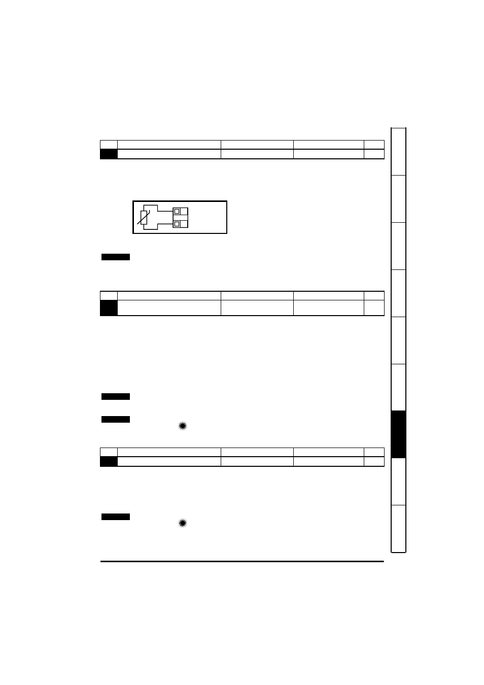
Motor thermistor input, connect as per diagram below
Fr
:
Frequency input.
Fr.hr
:High resolution frequency input.
Figure 7-11
Trip resistance: 3kΩ
Reset resistance 1k8
n=0
:
At zero speed
At.SP
: At speed
Lo.SP
: At minimum speed
hEAL
: Drive ok
Act
:
Drive active
ALAr
: General drive alarm
I.Lt
:
Current limit active
At.Ld
: At 100% load
USEr
: User programmable
Fr
:
Voltage proportional to motor speed
Ld
:
Voltage proportional to motor load
A
:
Voltage proportional to output current
Por
:
Voltage proportional to output power
USEr
: User programmable
No
Function
Range
Defaults
Type
34
Terminal B7 mode select
dig, th, Fr, Fr.hr
0:dig
RW
0V
Motor thermistor
input
T1
B7
If Pr 34 is set to th so that terminal B7 is used as a motor thermistor, the functionality of
terminal B7 as set-up with Pr 05, drive configuration, will be disabled.
When setting to th, press mode four times. Analog reference 2 will no longer be selected
as the speed reference. Analog reference 1 should be used.
NOTE
No
Function
Range
Defaults
Type
35
Digital output control (terminal B3)
n=0, At.SP, Lo.SP, hEAL,
Act, ALAr, I.Lt, At.Ld, USEr
0:n=0
RW
This parameter is automatically changed by the setting of Pr 12. When Pr 12
automatically controls the setting of this parameter, this parameter cannot be changed.
NOTE
A change to this parameter is only implemented if the drive is disabled, stopped or
tripped and the
STOP/RESET key is pressed for 1s.
NOTE
No
Function
Range
Defaults
Type
36
Analog output control (terminal B1)
Fr, Ld, A, Por, USEr
0:Fr
RW
A change to this parameter is only implemented if the drive is disabled, stopped or
tripped and the
STOP/RESET key is pressed for 1s.
NOTE