Diagnostics applications, Test startup and vehicle connection, Step 1: connect the cable – Autel MaxiDAS DS708 User Manual
Page 30
24
3. Diagnostics Applications
3.1. Test Startup and Vehicle Connection
3.1.1. Step 1: Connect the Cable
The method used to connect the scan tool to a vehicle’s DLC depends on the
vehicle’s configuration as follows:
A vehicle equipped with an On Board Diagnostics Two (OBD II) vehicle
management system supplies both communication and 12-volt power
through a standardized J-1962 data link connection (DLC).
A vehicle not equipped with an OBD II system supplies communication
through a DLC connection and sometimes supplies 12-volt power
through the cigarette lighter receptacle or a connection to the battery.
a. OBD II Vehicle Cable Connection
This type of connection generally requires the 15-pin main cable and an
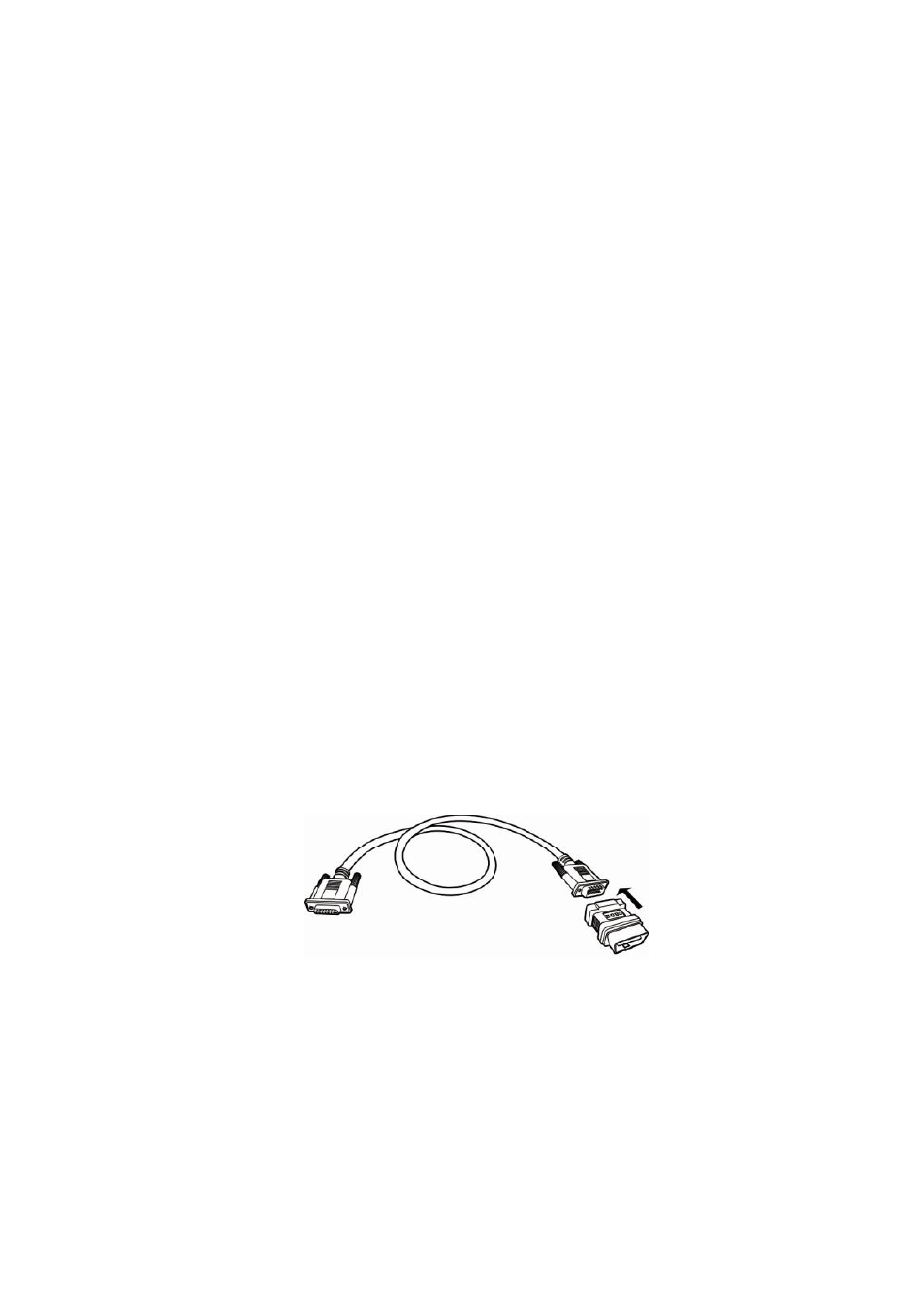
OBD II adapter. To connect the 15-pin main cable, please follow these steps:
Locate the required OBD II adapter and connect it into the 15-pin male
connector of the main cable.
Figure 3.1: OBD II Adapter Connection to the DB15 Main Cable
Connect the cable’s 15-pin female adapter to the DB 15-pin port on the
top of the scan tool. Finger tighten the connecting screws.