Rear front, 6 edh4 transponder pin connections, 7 upgrading the edh4 firmware – Alpha Technologies XP-EDH4 - Technical Manual User Manual
Page 74: 0 configuration and operation, continued
74
745-419-B0-001 Rev. A (11/2013)
3.0
Configuration and Operation, continued
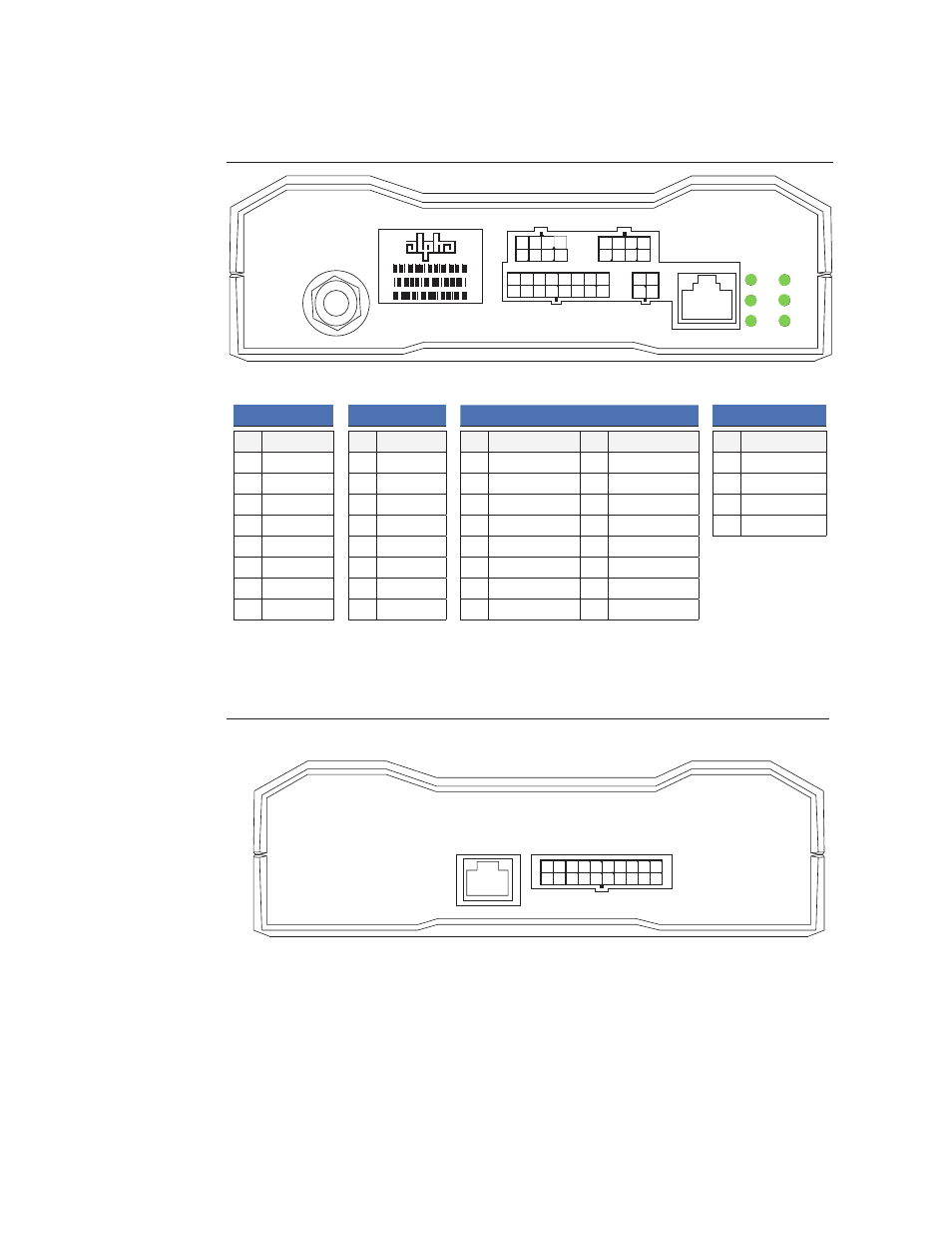
3.10.6 EDH4 Transponder Pin Connections
BATT C/D
Pin Description
1
GND
2
1C
3
2C
4
3C
5
1D
6
2D
7
3D
8
4
NOTE:
1C = Battery 1, String
C, where Battery 1 is
at the bottom of the
string.
1
1
4
3
1 2
2
2 3
3
4
4
5
6
7
8
8
7
6
5
9 10 11 12
16
15
14
13
PWR SUPPLY
Pin Description
Pin Description
1
GND
9
Digital Input
2
Digital Output
10
Analog DC Input
3
Digital Output
11
Analog DC Input
4
Digital Input
12
Analog DC Input
5
Digital Input
13
Analog DC Input
6
Digital Input
14
Analog DC Input
7
Digital Input
15
Analog DC Input
8
Digital Input
16
Analog DC Input
CNTL
Pin Connection
1
GND
2
+5V
3
Digital Output
4
Digital Input
BATT A/B
Pin Description
1
GND
2
1A
3
2A
4
3A
5
1B
6
2B
7
3B
8
4
NOTE:
1A = Battery 1, String
A, where Battery 1 is
at the bottom of the
string.
REAR
FRONT
20
19
18
17
14 15 16
12
11
10
9
5 6 7 8
4
1 2 3
13
3.10.7 Upgrading the EDH4 Firmware
The firmware in the EDH4 transponder can be upgraded in the same fashion as any other
DOCSIS-compliant cable modem.
1
2
3
4
5
6
7
8