4 powering the edh4 transponder, 5 connector & led summary – Alpha Technologies XP-EDH4 - Technical Manual User Manual
Page 11
11
745-419-B0-001 Rev. A (11/2013)
1.4 Powering the EDH4 Transponder
Power the EDH4 transponder through one of the following transponder interfaces:
• Battery Interface Connection (BAT A/B)
• Battery Interface Connection (BAT C/D)
• HMS interface port (HMS)
• Auxiliary (generic) I/O (AUX I/O)
In the event of multiple sources of power (e.g., batteries and HMS port), the highest voltage will source
power to the transponder.
Installation Notes:
• Before field installation, the transponder’s MAC address should be loaded into the DHCP server,
and DOCSIS configuration file options should be set. This permits on-site verification of network
connectivity and data, preventing the need for an additional visit to the site should there be a problem
with the installation.
• Do not place the transponder on top of the power supply or batteries.
• Make all battery harness connections and connect the interface cable to the power supply before
connecting the cables to the transponder.
1.5 Connector & LED Summary
1.0
Introduction, continued
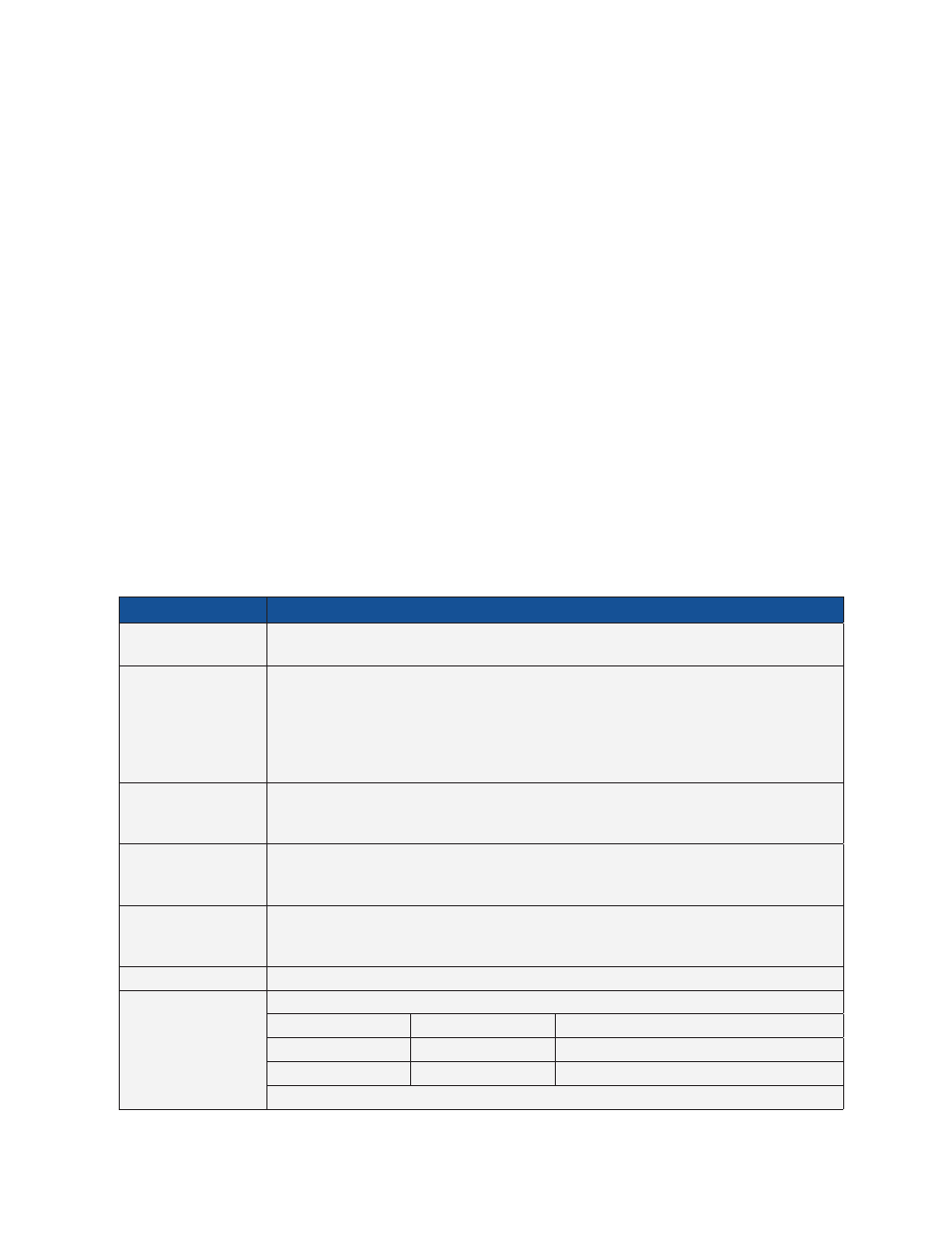
Connector
Description
RF
The RF connector, the physical interface to the cable plant, exchanges RF data between the CMTS
and the transponder.
BAT A/B and BAT C/D There are two battery interface connectors to the battery strings. The connection labeled BAT A/B
interfaces to battery strings A and B. The connection labeled BAT C/D interfaces to battery strings
C and D. The EDH4 also receives power through these interfaces when they are used to measure
battery data. When the transponder is used to monitor an SCTE HMS power supply, battery data
can be gathered through the transponder's SCTE HMS connection (labeled HMS), or through the
BAT A/B and BAT C/D ports.
AUX I/O
The AUX I/O connector provides a generic input/output port to allow monitoring of co-located
equipment if required. Pin 19 allows powering the unit with 24 - 60 Vdc. Also, 3.3 volt power is
available on pin 20. Common ground is on pin 1.
HMS
The HMS connector on the back of the transponder accepts the standard SCTE HMS-022 Interface
Cable, and exchanges ANSI/SCTE HMS digital data between the transponder and a power supply
with a SCTE HMS-022 interface.
PWR SUPPLY
The main power supply interface is through this connector. This connector delivers both digital and
analog signals to the transponder for monitoring as well as digital outputs and an interface to an
external temperature sensor and/or line voltage sense transformer, if applicable.
CNTL
CNTL provides connection to a battery mat heater control.
LED Indicators
The EDH4 transponder includes six green LEDs:
• STAT
• US
• ELINK
• DS
• ONLINE
• PWR
The LEDs indicate transponder status. See Section 3.1 Checking the LEDs.
Table 1-1, EDH4 Connector Functionality