10 transponder cabling – Alpha Technologies XP-EDH4 - Technical Manual User Manual
Page 71
71
745-419-B0-001 Rev. A (11/2013)
The batteries in each string are numbered sequentially from 1 through 2 (in the case of 24 volt
strings), from 1 through 3 (in the case of 36 volt strings), and from 1 through 4 (in the case of
48 volt strings) where Battery 1 of any string type is the designator of the first battery when
referenced from battery common or the negative end of the string.
The transponder reports the voltage of each monitored/measured battery with a resolution of 0.1
VDC with a maximum measurement accuracy tolerance of ±2% from the nominal 12V battery
measurement.
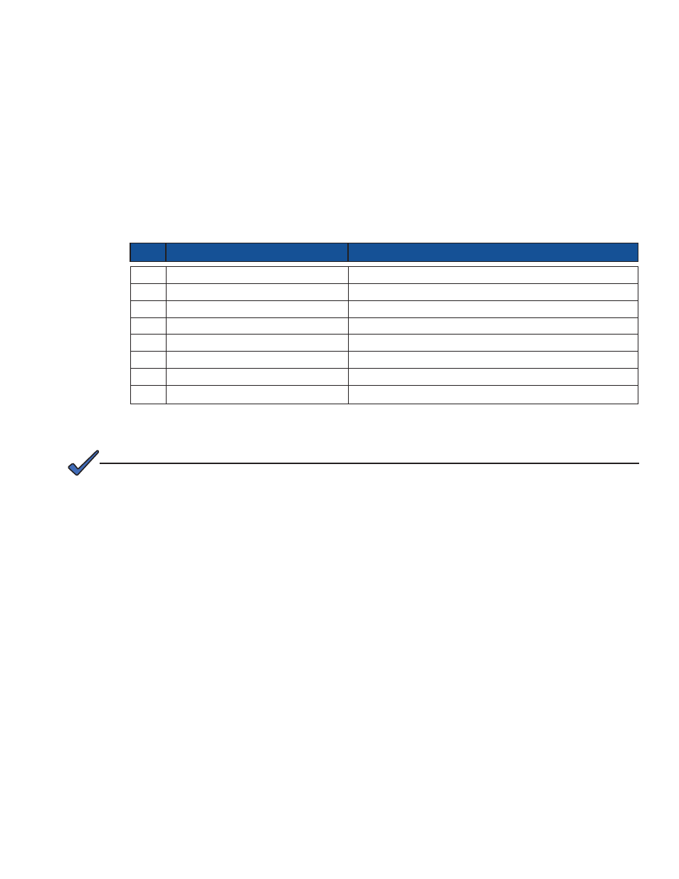
Table 3-11, Battery Connector Pinouts
PIN NAME
DEFINITION
1
COMMON
MOST NEGATIVE TERMINAL OF BOTH BATTERY STRINGS
2
BATT 1 POS. A/C 12 V STRINGS
POSITIVE TERMINAL OF BATTERY 1 IN THE A OR C STRING
3
BATT 2 POS. A/C 24 V STRINGS
POSITIVE TERMINAL OF BATTERY 2 IN THE A OR C STRING
4
BATT 3 POS. A/C 36 V STRINGS
POSITIVE TERMINAL OF BATTERY 3 IN THE A OR C STRING
5
BATT 1 POS. B/D 12 V STRINGS
POSITIVE TERMINAL OF BATTERY 1 IN THE B OR D STRING
6
BATT 2 POS. B/D 24 V STRINGS
POSITIVE TERMINAL OF BATTERY 2 IN THE B OR D STRING
7
BATT 3 POS. B/D 36 V STRINGS
POSITIVE TERMINAL OF BATTERY 3 IN THE B OR D STRING
8
BATT 4 POS. A/B OR C/D 48V STRINGS POSITIVE TERMINAL OF BATTERY 4 IN THE A/B OR C/D STRING
3.0
Configuration and Operation, continued
3.10 Transponder Cabling
3.10.1 Battery Cable
Cable Pinout Details
Refer to the illustration at the end of this chapter to see the connector locations on the EDH4
transponder.
Each battery connector can connect/monitor up to two series of battery strings, typically in 24,
36, or 48 Volt configurations, for a maximum of four strings per transponder. Following is the pin
number configuration chart.
The maximum voltage tolerable without damage to the transponder on any pin of the battery interface
connectors is 64 Vdc.
NOTE: