3 non-hms alpha power supplies – Alpha Technologies XP-EDH4 - Technical Manual User Manual
Page 21
21
745-419-B0-001 Rev. A (11/2013)
Installation Procedure:
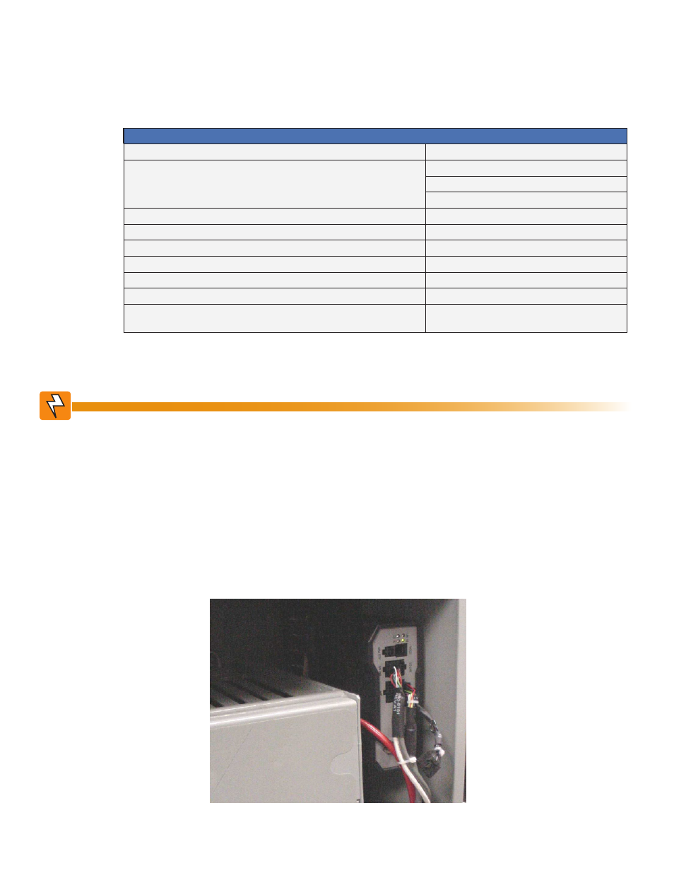
1. Remove the EDH4 transponder and cabling from its shipping package.
2. Insert the 16-pin connector of the EDH4 Power Supply Interface Cable into the transponder’s
PWR SUPPLY interface port.
3. Install the EDH4 into the power supply cabinet using the adhesive fasteners on the bottom of
the transponder. Refer to Figure 2-3 for a possible mounting location in the enclosure.
2.0
Installation, continued
2.3 Non-HMS Alpha Power Supplies
2.3.1 AM Series with RPM Interface
Required Materials
RF Cable
Customer supplied
Battery Sense Wire Harness for:
36V single string, 6', Alpha p/n 874-842-21
36V single string, 9', Alpha p/n 874-842-27
36V dual string, 9', Alpha p/n 874-842-28
AM Series Power Supply Interface Cable
Alpha p/n 875-335-21 (for RPM interface)
Battery Heater Mat Control Cable (optional)
Alpha p/n 875-627-20
Ethernet Cable (optional)
Alpha p/n 875-734-19
External Temp Probe (optional)
Alpha p/n 745-178-21
Vin Sense (optional; requires 120VAC receptacle)
Alpha p/n 875-493-21
Surge Protector w/Ground Block
Alpha p/n 162-028-10
In Line Lightning Arrestor w/pass through (130V) L-G, L-N, N-G
Alpha p/n 162-046-10 (not compatible with
240V circuits/receptacles)
Fig. 2-5, Installing the EDH4
Before beginning this installation, verify power is removed from the power supply. Installation
should be performed only by a qualified service personnel.
WARNING!