Alpha Technologies XP-EDH4 - Technical Manual User Manual
Page 34
34
745-419-B0-001 Rev. A (11/2013)
2.0
Installation, continued
2.7 Lectro CPR Power Supply with Existing Level 2 Card, continued
Installation Notes:
• Before field installation, the transponder's MAC address should be loaded into the DHCP server,
and DOCSIS configuration file options should be set. This permits on-site verification of network
connectivity and data, preventing the need for an additional visit to the site should there be a problem
with the installation.
• Do not place the transponder on top of the power supply or batteries.
• Make all battery harness connections and connect the interface cable to the power supply before
connecting the cables to the transponder.
Removal or installation of the Level 2 interface card requires powering down the supply. An alternate
source of power (such as a service power supply) is recommended if service is to be maintained during this
procedure. Alpha does not supply new Level 2 interface cards with the DB-9 Serial Port.
Connection of the battery sense harness requires disconnecting the standby batteries; as a result service
would be interrupted in the event of a utility outage.
WARNING!
Installation Procedure:
1. Turn off the battery circuit breaker on the power supply and unplug the line cord.
2. Disconnect the batteries from the left side of the power supply.
3. Install the battery sense harness as shown in the instructions included with the harness.
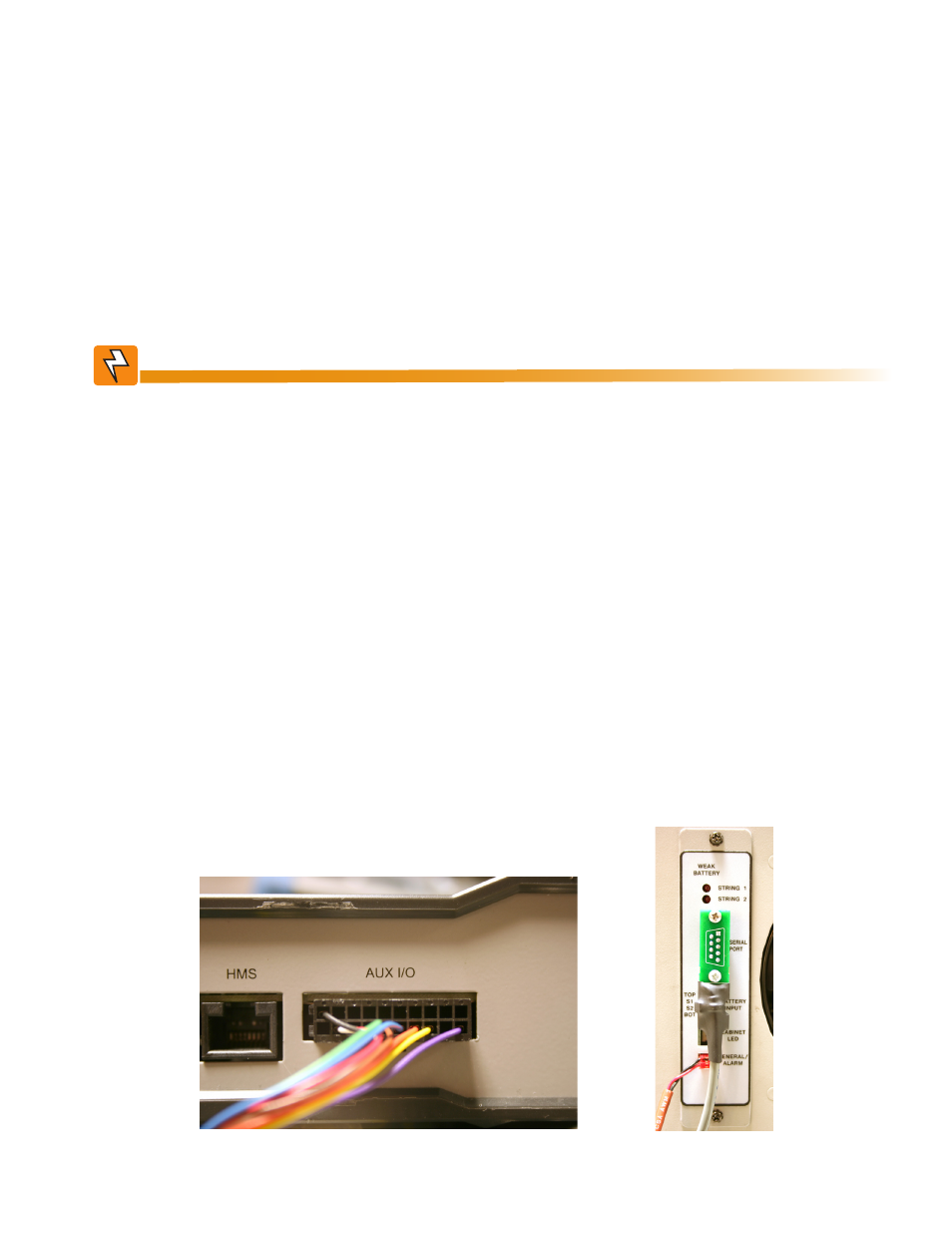
4. Connect the 20 pin connector on the other end of the interface cable to the AUX I/O connector on the
rear panel of the EDH4 transponder (Fig. 2-14).
5. Connect the 9 pin connector of the interface cable, and secure with the two screws. Connect the
enclosure tamper switch (if present) to the “GENERAL/ALARM” connector (Fig. 2-15).
6. Connect the RF drop to the RF connector on the transponder, and battery sense cable to the BAT A/B
connector (and BAT C/D for 3rd and 4th battery installations) (see Fig. 2-17, Fig. 2-18, Fig. 2-19, or
Fig. 2-20, as applicable).
7. Connect the batteries to the left side of the power supply, and plug in the input power cord to the power
supply (see
Section 2.7, Battery String Connections).
8. Turn the battery circuit breaker on.
Fig. 2-16, AUX I/O Connector
Fig. 2-17, General/Alarm Connector