Error detection and elimination – Elmo Rietschle 2FC4...-1CB User Manual
Page 62
8
Error detection and elimination
610.00260.40.000 · 05.2014
62
/
74
© Gardner Denver Deutschland GmbH
List of errors and system errors
When an error occurs, the inverter switches off; for the corresponding error num-
bers, refer to the flash code table or the PC tool.
Error messages can only be acknowledged when the error is no longer pre-
sent.
!
Error messages can be acknowledged as follows:
1. Digital input (programmable)
2. via the hand-held unit MMI
3. Automatic acknowledgement (parameter 1,181)
4. Switching the device on and off
5. via fieldbus (CANOpen, Profibus DP, EtherCAD)
Below is a list of possible error messages. For errors not listed here, please con-
tact the manufacturer.
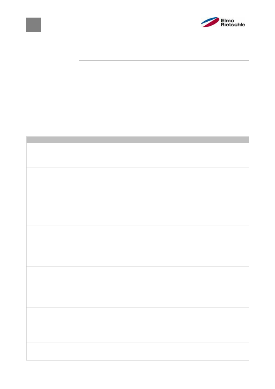
Error detection
No. Error name
Error description
Possible cause / remedy
1
Low voltage 24 V application
Supply voltage of the applica-
tion is less than 15 V
Overload of the 24 V supply
2
Over-voltage 24 V application
Supply voltage of the applica-
tion is greater than 31 V
Internal 24 V supply is not OK or
external power supply is not OK
3
Version error of client PLC
The version of the client PLC
does not match the device
firmware
Check the version numbers of
the customer PLC and device
firmware
4 Communication
applica-
tion<>performance
The internal communication
between the application and
power printed circuit board is
out of order
EMC interference
5 Parameters
distributor
The internal distribution of the
parameters during the initialisa-
tion has failed
Parameter set is incomplete
6 Timeout
performance
The
power unit does not re-
spond
Operation with 24 V without
power supply
7
Cable breakage analogue input
1 (4 - 20 mA / 2 - 10 V)
Current or voltage is less than
the lower limit of the analogue
input 1 (this error monitoring is
activated by setting the parame-
ter 4,021 to 20%)
Cable breakage, defective ex-
ternal sensor
8
Cable breakage analogue input
2 (4 - 20 mA / 2 - 10 V)
Current or voltage is less than
the lower limit of the analogue
input 2 (this error monitoring is
activated by setting the parame-
ter 4,021 to 20%)
Cable breakage, defective ex-
ternal sensor
9
Blocking detection
The drive shaft of the motor is
blocked. 5.080
Remove blockage
10
Overtemperature of drive con-
troller application
Internal temperature too high
Insufficient cooling, low speed
and high torque, clock fre-
quency too high
11
Bus timeout
No response from the bus de-
vice or HAND-HELD UNIT MMI /
PC
Check bus wiring
12 Confirmation
error
The number of max. automatic
acknowledgements (1,182) has
been exceeded
Check the error history and
eliminate errors
8.2