Installation – Elmo Rietschle 2FC4...-1CB User Manual
Page 23
Installation
5
© Gardner Denver Deutschland GmbH
23
/
74
05.2014 · 610.00260.40.000
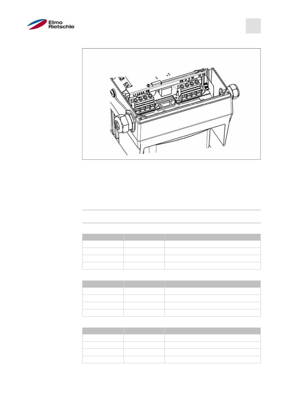
Power connection of size D
Power connection BG D
1. Unscrew the four screws from the housing cover of the drive controller and
remove the cover.
2. Run the mains cable through the threaded cable gland and connect the
phases with the contacts L1, L2, L3 for 400 V and the buried cable with the
PE contact on the terminal. The threaded cable gland provides cable relief,
the PE connection line must be connected as a leading contact (significantly
longer)!
When connecting a braking resistor to an optional brake module, shielded
and double-insulated cables must be used.
3 ~ 400 V terminal assignment X1
Terminal no.
Designation
(Terminal) assignment
1
L1
Mains phase 1
2
L2
Mains phase 2
3
L3
Mains phase 3
4
PE
Buried cable
DC supply 250 to 750 V terminal assignment X1
Terminal no.
Designation
(Terminal) assignment
1
L1
DC network (+) (565V)
2
L2
Not assigned.
3
L3
DC network (-)
4
PE
Buried cable
Motor terminal assignment X4
Terminal no.
Designation
(Terminal) assignment
1
PE
Buried cable
2
U
Motor phase 1
3
V
Motor phase 2
4
W
Motor phase 3
5.3.4