Installation, Notice – Elmo Rietschle 2FC4...-1CB User Manual
Page 24
5
Installation
610.00260.40.000 · 05.2014
24
/
74
© Gardner Denver Deutschland GmbH
Connections for braking resistor
Terminal assignment for braking chopper
Terminal no.
Designation
(Terminal) assignment
1
B+
Connection of braking resistor (+)
2
B-
Connection of braking resistor (-)
Control terminals
Control terminals of the standard application card
NOTICE
Risk of coupling of external signals!
Use shielded control wires.
1. Pass the required control wires through the threaded cable glands into the
housing.
2. Connect the control wires according to the picture and/or table. To do this,
use shielded control wires.
3. Put the lid on the housing of the drive controller and screw it in place.
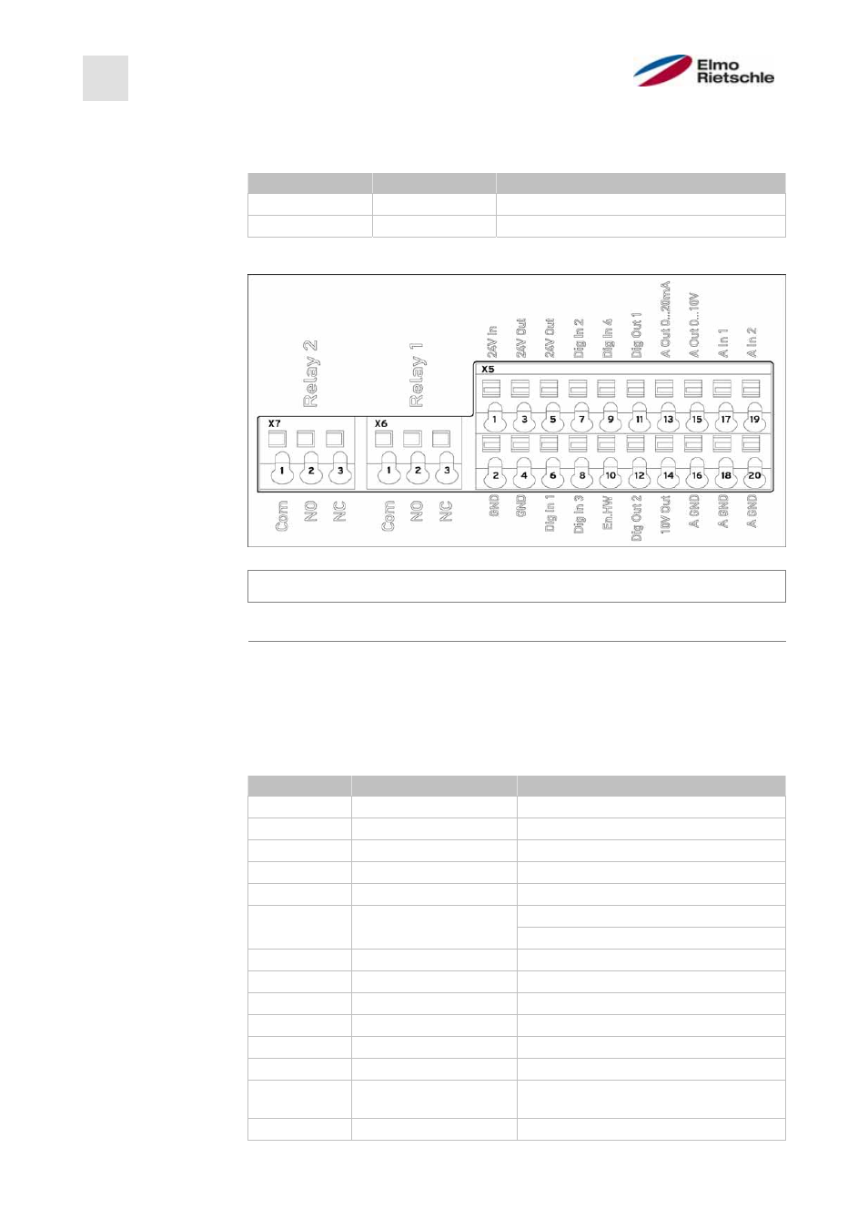
Terminal assignment X5 of the standard application card
Terminal no. Designation
(Terminal) assignment
1
24 V In
External power supply
2
GND (Ground)
Ground
3
24 V Out
Internal power supply
4
GND (Ground)
Ground
5
24 V Out
Internal power supply
6
Dig. In 1
fixed frequency 1/3 (parameter 1,100)
Software release (parameter 1,131)
7
Dig. In 2
fixed frequency 2/3 (parameter 1,100)
8
Dig. In 3
Fault reset (parameter 1,180)
9
Dig. In 4
External error (parameter 5,010)
10
En -HW (release)
Hardware release
11
Dig. Out 1
Ready (parameter 4,150)
12
Dig. Out 2
Operation (parameter 4,170)
13
A. Out 0 ... 20 mA
Actual frequency value (parameter
4,100)
14
10 V Out
For external voltage divider
5.3.5
5.3.6