Installation – Elmo Rietschle 2FC4...-1CB User Manual
Page 20
5
Installation
610.00260.40.000 · 05.2014
20
/
74
© Gardner Denver Deutschland GmbH
Mechanical installation of size D
For mechanical installation of the drive controller, proceed as follows:
1. Open the standard motor connection box.
2. Remove the fastening screws securing the housing and remove the housing.
Be careful not to damage the gasket.
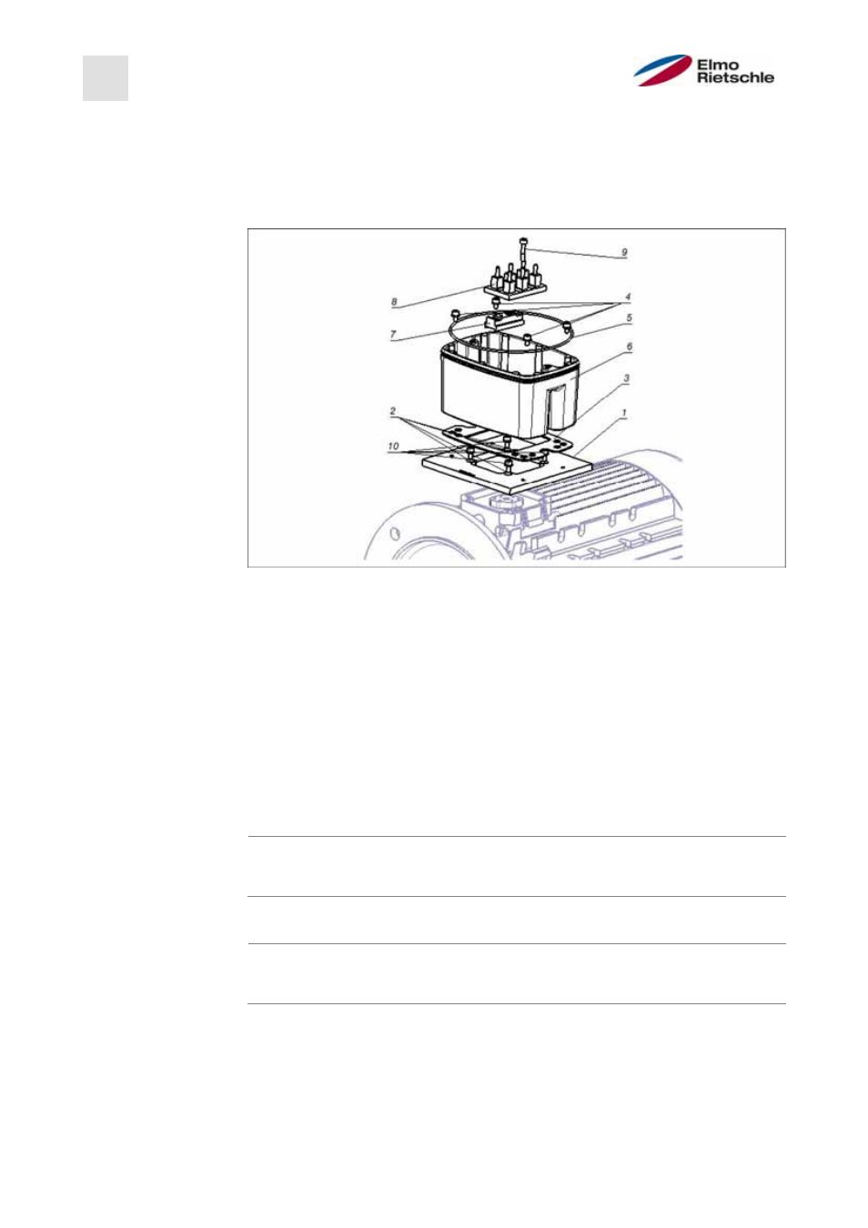
Assembly sequence: Junction box - adapter plate (BG D)
1 Adapter plate option (variant)
6
Support the drive controller /
adapter plate
2 Motor-dependent holes
7 Terminal board expansion option
3 Seal
8
Original terminal board (not in-
cluded in the delivery)
4
Fastening screws with spring
elements
9 Elongated screw option (for 7)
5 O-ring- gasket
10
Fastening screws with spring
elements option
The standard adapter plate is an adapter plate whose lower part has not
been refinished. No holes are drilled.
For the motors supplied, you can order adapter plates from the manufacturer.
3. Adjust them to the adapter plate (1) by drilling appropriate holes (2) in them
for attachment to the motor.
The system start-up engineer is responsible for maintaining the protection
class for the gasket of the adapter plate on the motor.
For questions, please contact your sales representative.
4. Insert the gasket (3).
5. Screw the adapter plate onto the motor using the four fastening screws and
the four spring elements (10) (torque: M4 with 2.4 Nm [1.77 ft lbs], M5 with
5.0 Nm [3.70 ft lbs], M6 with 8.5 Nm [6.27 ft lbs]).
5.3.2