Error detection and elimination – Elmo Rietschle 2FC4...-1CB User Manual
Page 61
Error detection and elimination
8
© Gardner Denver Deutschland GmbH
61
/
74
05.2014 · 610.00260.40.000
Error detection and elimination
In this chapter, you will find
▪ Display of the LED flash codes for error detection
▪ Description of error detection using PC tools
▪ List of errors and system errors
▪ Notes on error detection using the HAND-HELD UNIT MMI
WARNING
Risk of injury and danger of electric shock!
The non-observance of warnings can result in severe bodily injury or sub-
stantial property damage.
1. Repairs on the device may only be carried out by the manufacturer.
2. Any defective parts or components must be replaced using parts included in
the relevant spare parts list.
3. Prior to opening, assembly or disassembly, the drive controller must be
unlocked.
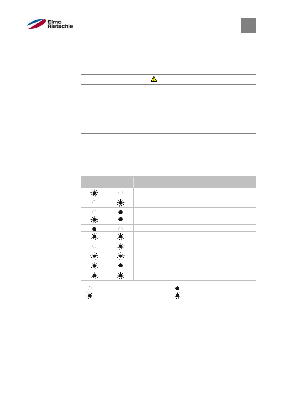
Display of the LED flash codes for error detection
When an error occurs, the LEDs on the drive controller display a flash code via
which the error can be diagnosed.
The following table gives an overview.
LED flash codes
Red LED
Green
LED
Status
Bootloader active (flashing alternately)
Ready for operation (enable En_HW for operation)
Operation
Warning
Error
Motor data label
Initialisation
Firmware update
Bus error operation
Bus error ready for operation
LED off
LED on
LED flashes
LED flashes quickly
8
8.1