Preliminar y, Programming and control, cont’d – Extron Electronics System 5 IP Series User Guide User Manual
Page 90
SIS
™
Programming and Control, cont’d
System 5 IP • SIS
™
Programming and Control
5-34
PRELIMINAR
Y
Command/response table for special function SIS commands, continued
Command
ASCII Command Response
X?
values
(host to MLC)
(MLC to host)
and additional descriptions
Button associations (virtual mapping) for an IRCM-DV+
By design an IRCM-DV+ can be assigned paired module addresses (by DIP switch) of either 1&2 or 3&4 only. It cannot
be assigned to addresses 2&3 or 1&4. The odd-numbered module address (1 or 3) is reserved for DVD control, the even-
numbered module address (2 or 4) is for VCR control. The address DIP switches must be set in order for the System 5 IP
to recognize and reserve memory space for the module. Refer to the Control Modules User’s Manual.
To use an optional IRCM-DV+ with a System 5 IP, you’ll need to associate the DVD portion of this module with a
System 5 IP input selection button
, and also associate the VCR portion with a different System 5 IP input selection
button
. The associated button must be selected (pressed) in order to activate and use the VCR portion or the DVD
portion of the module. You cannot activate both parts (VCR and DVD) at the same time. If you do not associate (map)
the IRCM-DV+’s addresses (1&2 or 3&4) with System 5 IP buttons, you cannot activate and use either the DVD or the
VCR part of the IRCM-DV+.
You cannot assign both the DVD and VCR portions to the same System 5 IP input selection button.
If two IRCM-DV+ modules are connected to the switcher, each module addresses (1, 2, 3, 4)
should be assigned to a different button on the switcher.
However, the DVD and VCR parts of the IRCM-DV+ can be assigned to the same input.
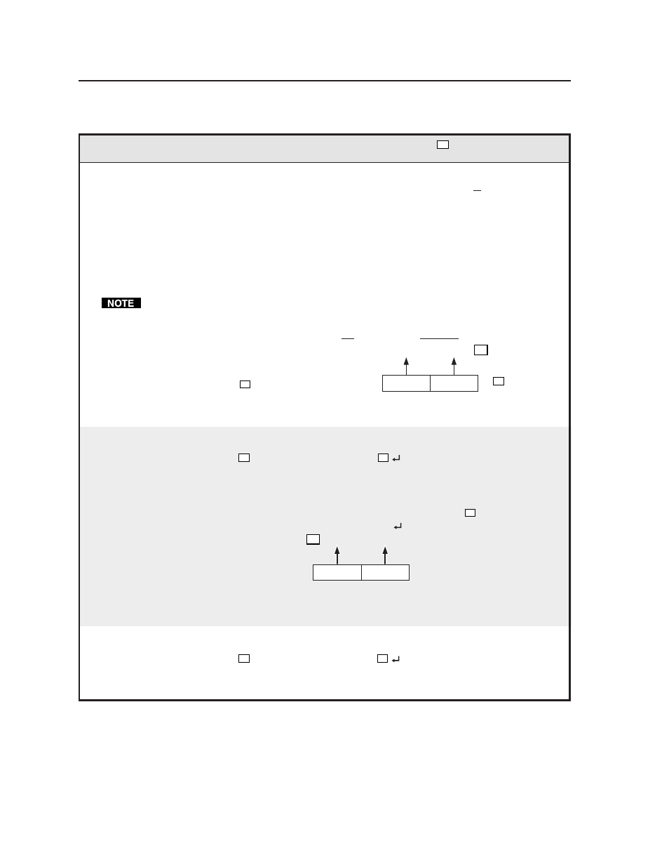
Here’s how to determine the value of
X?
for the following commands:
Button to
associate the
VCR
half (even
address) with
Button to
associate the
DVD
half (odd
address) with
A
(A x 16) + (B) =
B
X?
X?
will be a decimal
number from
000 to 237.
IRCM-DV+ address 2, address 1 button association
Associate switcher inputs/buttons w/IRCM-DV+
24
X?
*25 #
DVA_VMap*
X?
Associate specific System 5 IP/
SCP 150 input selection buttons
with the VCR and DVD halves
of the IRCM-DV+ which has
DIP switch-based addresses of 1
and 2.
X?
can be from 0 to 237.
Example:
52*25#
DVA_VMap*052
Associate the switcher’s input 4
button with IRCM-DV+
address 1 (DVD functions) and
System 5 IP input 3 button with
IRCM-DV+ address 2 (VCR
functions). See the illustration
at left.
Button to
associate the
VCR
half
(even address,
2 or 4) with
Button to
associate the
DVD
half
(odd address,
1 or 3) with
3
= (3 x 16) + (4) = 52
4
X?
IRCM-DV+ address 4, address 3 association
Associate System 5 IP inputs/buttons w/IRCM-DV+
24
X?
*26#
DVB_VMap*
X?
Associate System 5 IP buttons
with the VCR & DVD parts of
an IRCM-DV+ which has DIP
switch-set addresses of 3 and 4.